Modulation
What modulation is
In Session 1, the ADSR envelope controlled the VCA’s volume and the VCF’s cutoff — one signal changing another over time. That’s modulation: using a control signal to continuously vary a parameter that would otherwise stay fixed.
Without modulation, every parameter is static — the filter cutoff sits at one frequency, the volume stays at one level, the pitch holds one note. The sound is frozen. Modulation is what makes a patch move. An LFO sweeping a filter cutoff, an envelope shaping volume, a random voltage wiggling pitch — these are all the same idea: one signal riding on top of another to create change over time.
The three things that define a modulation:
- Source — what generates the control signal (LFO, envelope, sequencer, noise, another oscillator)
- Destination — the parameter being changed (filter cutoff, VCA level, oscillator pitch, any knob with a CV input)
- Depth — how much the source affects the destination, usually set by an attenuverter or a dedicated depth knob
This session explores different modulation sources beyond the ADSR — LFOs, function generators, multi-wave modulators, wavetables — and how the choice of source shapes the character of the movement.
Starter patch
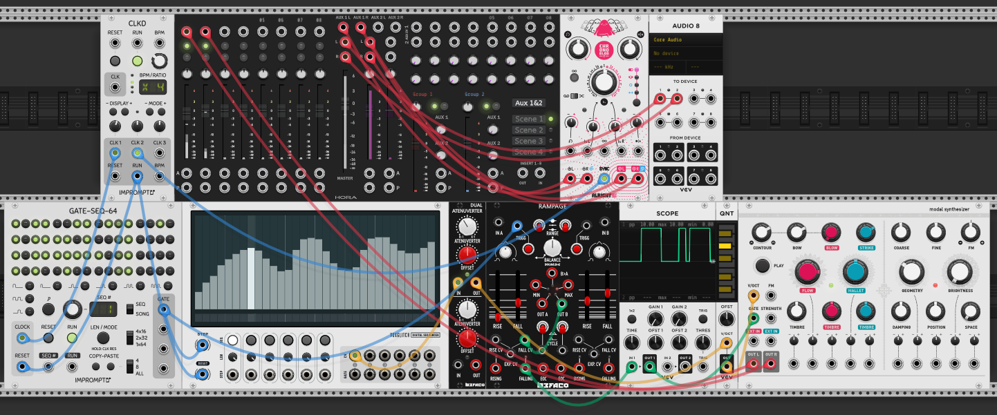
The starter patch for modulation builds on the sequencing setup from Session 2. CLKD clocks the GATE-SEQ-64, which drives a step sequencer. Pitch CV goes through the QNT (quantizer) to the Modal Synthesizer’s V/OCT input (yellow cables). Gates trigger the Modal Synthesizer’s GATE STRENGTH input (blue cables). Audio routes from the Modal Synthesizer through the Hora mixer to Audio 8, with Chronoblob on the aux send for clock-synced delay.
Two modulation utility modules sit in the middle: a Dual Attenuverter (Befaco) and Rampage (Befaco). Rampage’s side A has CYCLE engaged, and its OUT B feeds back into its own FALL CV input — a self-patch that makes the fall time vary each cycle, producing an evolving, organic modulation shape instead of a static envelope.
| From | To | Cable | Role |
|---|---|---|---|
| CLKD CLK | GATE-SEQ-64 CLOCK | blue | Master clock drives gate pattern |
| GATE-SEQ-64 | Step sequencer | blue | Gate pattern filters clock to sequencer |
| Step sequencer | QNT V/OCT | yellow | Raw pitch CV to quantizer |
| QNT OUT | Modal Synth V/OCT | yellow | Quantized pitch to synth |
| Gate signal | Modal Synth GATE STRENGTH | blue | Triggers the physical model |
| Modal Synth OUT | Hora mixer | red | Audio to mixer |
| Hora mixer L/R | Audio 8 | red | Audio to speakers |
| Hora mixer AUX | Chronoblob | red | Send effect — clock-synced delay |
| Rampage OUT B | Rampage FALL CV | green | Self-patch — fall time modulates itself each cycle |
LFO as modulation source
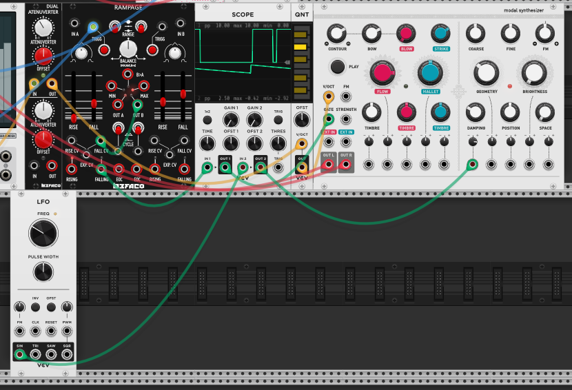
Adding a VCV LFO module as a dedicated modulation source. The LFO’s SIN output goes through the Dual Attenuverter and into the Modal Synthesizer’s DAMPING parameter (green cables — modulation path).
The attenuverter is critical here: it must be turned away from noon (the center position) or the modulation has zero depth and you won’t hear any change. At noon the attenuverter multiplies the signal by zero — nothing passes through. Turn clockwise for positive modulation (LFO up = more damping), counter-clockwise for inverted modulation (LFO up = less damping). The further from noon, the deeper the effect.
The Scope displays the LFO’s sine waveform — a smooth, continuous shape. As it cycles, you hear the Modal Synthesizer’s damping sweep up and down, changing how quickly the resonance of the physical model decays. At slow LFO rates it’s a gentle breathing quality; faster rates create a more obvious wobble.
The LFO has four waveshape outputs at the bottom — SIN, TRI, SAW, SQR — each giving the modulation a different character. SIN is the smoothest sweep, SQR snaps between two extremes, SAW and TRI fall in between.
| From | To | Cable | Role |
|---|---|---|---|
| LFO SIN | Dual Attenuverter IN | green | Sine wave modulation source |
| Dual Attenuverter OUT | Modal Synth DAMPING | green | Scaled modulation to damping parameter |
Rampage as LFO
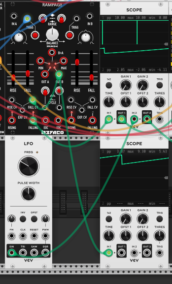
Rampage with CYCLE engaged functions as an LFO. The top scope shows Rampage’s OUT B output — a repeating rise/fall shape, more angular than a sine. The bottom scope shows the dedicated LFO’s sine output — smooth and symmetrical. Both are free-running modulation sources that can be routed to the same destinations.
The difference is in the shape and control. The LFO gives you clean waveshapes (sine, triangle, saw, square) with a single frequency knob. Rampage gives you independent control over rise and fall times, so you can make asymmetric shapes — fast attack with slow decay, or vice versa. Combined with the self-patch from the starter patch (OUT B → FALL CV), Rampage’s shape evolves over time in ways a standard LFO won’t.
Rampage is a function generator, not an envelope generator. At its core, a function generator is a slew limiter that processes external signals — it can smooth incoming CV for portamento effects, the same way a dedicated slew limiter does (Session 13 covers slew limiters in depth). The distinction from an envelope generator: a function generator only needs a trigger, not a gate — it completes its full rise/fall cycle regardless of how long the gate stays open. It fires, runs its shape, and finishes. An envelope generator (like the ADSR) is gate-dependent — its sustain stage holds as long as the gate is high, and release only begins when the gate drops. All envelope generators are function generators, but not the other way around. A function generator has no sustain — it always runs to completion.
Some function generators also have a loop mode (like Rampage’s CYCLE button) that repeats the rise/fall cycle endlessly once triggered — effectively turning the function generator into an oscillator. At low speeds it behaves like an LFO; at high speeds it produces audio-rate signals. Many also have an EOC (end of cycle) output that fires a trigger each time the function completes — this can act as a clock, triggering other modules or even feeding back into itself to create self-playing patches. The clock speed depends on the function’s duration: longer rise/fall times mean a slower clock, shorter times mean a faster clock.
ADSR as modulation source
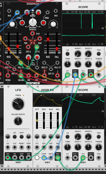
The ADSR (Session 1) is a third type of modulation source — but unlike the LFO and Rampage, it only fires when it receives a gate. One envelope per note, tied to the rhythm of the patch rather than cycling on its own.
The new detail here is how gate duration shapes the envelope. With a short trigger instead of a held gate, there’s no hold period — the envelope passes straight through attack → decay → release and the sustain knob does nothing. This is what controls whether a note is percussive (short gate, sustain skipped) or held (long gate, sustain matters).
Patching the ADSR to a parameter like DAMPING or GEOMETRY means the timbral change happens in lockstep with each note — unlike an LFO, which drifts against the rhythm independently.
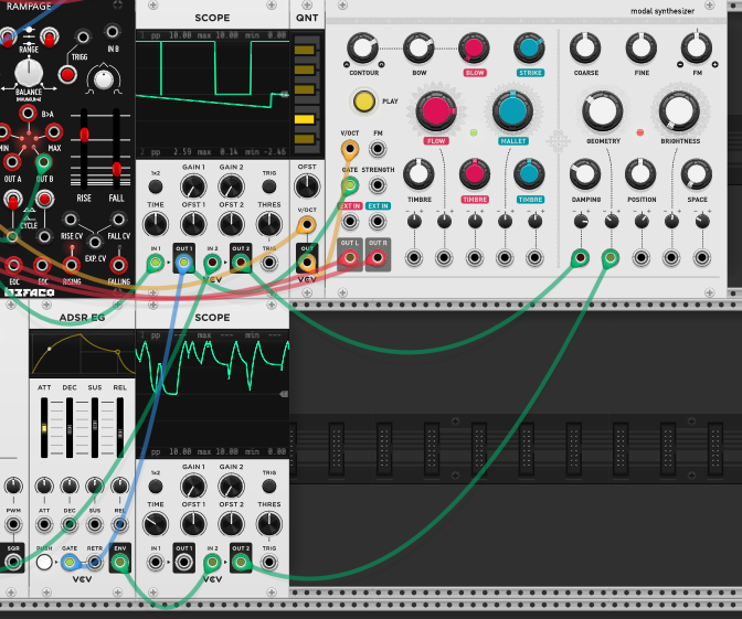
Here the ADSR’s envelope output is patched to the Modal Synthesizer’s GEOMETRY input (green cable). Each note triggers the ADSR, which sweeps the resonator’s geometry through its envelope shape — the result is a funky, morphing quality where the physical model’s structure shifts on every hit and settles back. The scope shows the envelope shape alongside the audio — you can see the modulation event coincide with each note.
Three modulation sources, three behaviours:
- LFO — free-running, continuous, periodic. Shape set by waveshape output (SIN/TRI/SAW/SQR)
- Rampage — free-running (with CYCLE), asymmetric rise/fall, can self-modulate for evolving shapes
- ADSR — gate-triggered, one-shot per note. Shape set by attack/decay/sustain/release knobs
Variations on the ADSR exist — the DADSR adds a Delay stage before attack, introducing a pause before the envelope begins (useful for delayed vibrato or staggered voice entries). Also note: if the gate is shorter than the attack time, the envelope never reaches its full peak — the attack is truncated, producing a quieter note.
Tidal Modulator — related multi-wave LFO
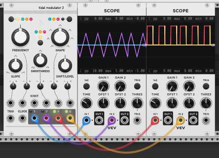
The Tidal Modulator 2 outputs four related waveforms from a single module. The left scope shows three smooth waves (blue, purple, yellow) — same frequency but offset in phase. The right scope shows pulse/square versions (red, orange). All four outputs are mathematically related, controlled by shared knobs: FREQUENCY sets the rate, SHAPE morphs the waveshape, SMOOTHNESS blends between angular and smooth, and SLOPE/SHIFT adjust the waveform symmetry and phase relationships.
The advantage over separate LFOs is coherence — patching these four outputs to four different parameters on a synth creates coordinated movement rather than independent drift. One knob change (FREQUENCY) shifts all four modulation rates together.
Wavetable LFO — custom modulation shapes
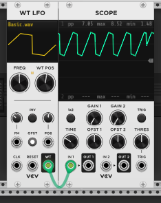
The WT LFO loads a wavetable file (here “Basic.wav”) and uses it as the modulation shape. The WT POS knob scrubs through the wavetable’s stored waveforms, and the scope shows the resulting shape — here a flat-topped waveform with sharp transitions, unlike anything a standard LFO’s SIN/TRI/SAW/SQR outputs would produce.
This means the modulation shape isn’t limited to the basic geometric waveforms. Any contour stored in the wavetable becomes available as a cycling modulation source — ramps with plateaus, multi-step shapes, or organic curves. FREQ still controls the rate, same as a regular LFO.
Mixing LFOs for complex modulation
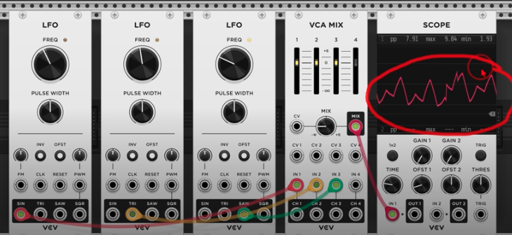
A fourth way to get complex modulation shapes: mix multiple simple LFOs through a mixer before routing to a destination. Three LFOs at different rates, each contributing a basic waveshape, sum together into an organic, irregular contour that none of them could produce alone. The mixer’s level controls set how much each LFO contributes to the final shape.
This is the same principle as audio harmonics — simple waves combine into complex ones — applied to modulation. It’s different from stacking multiple cables on one input (Session 1): mixing before routing gives you level control over each source. The result is a non-repeating modulation contour that feels more alive than a single LFO sweep.
Attenuation and attenuversion
The Dual Attenuverter has a second role beyond modulation depth control (covered above): scaling pitch CV from a non-quantized sequencer. When a sequencer outputs raw, non-quantized pitch values — continuous voltages rather than discrete semitone steps — the attenuverter sits between the sequencer output and the synth’s V/OCT input to control the pitch spread of the sequence.
Fully clockwise: the sequence plays at its full voltage range, producing wide intervals. Turning toward noon compresses the range — the same sequence pattern but with smaller intervals, until at noon the pitch collapses to a single note (zero multiplier, same as with modulation). Past noon into counter-clockwise territory, the pitch contour inverts — what was ascending becomes descending — and turning further from noon widens the inverted range.
The attenuverter’s offset knob shifts the entire modulation range up or down in voltage. The main knob controls how wide the pitch sweep is; the offset controls where that sweep is centered. This is different from the VCO’s frequency knob — that sets the base pitch of the oscillator itself. Use VCO frequency for tuning the voice, use the attenuverter offset for positioning where the modulation sits.
The quantizer (Session 2) works together with the attenuverter in this pitch path. What’s new here is how you choose the scale: the highlighted notes on the QNT module define the set of allowed pitches. Highlight C, D, E, G, A and every note gets pulled to pentatonic. Change the selection to C, E♭, F, G, B♭ and the same sequence becomes minor pentatonic. The sequencer pattern stays identical; the quantizer reinterprets it through a different scale.
The two modules divide the work: the attenuverter controls how far apart the raw voltages are (pitch spread), and the quantizer decides which actual notes those voltages land on (scale). Compress the range with the attenuverter and the same sequence might only span a third instead of two octaves — but still landing on scale-correct notes. The Dual Attenuverter is attached to the non-quantized sequencer: it gives continuous control over how melodically spread-out a sequence is, and whether its contour runs in the original or inverted direction.
The Dual Attenuverter module is an attenuverter — the noon-to-clockwise range attenuates, noon-to-counter-clockwise attenuates and inverts.
Clocked LFO modulation — hi-hat morph
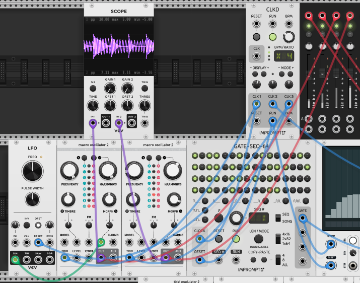
A new patch with two Macro Oscillator 2 modules (based on Mutable Instruments Plaits). The left oscillator is set to a hi-hat model. The LFO is clock-synced via CLKD — a blue cable from the clock into the LFO’s CLK input — so its cycle rate locks to the patch tempo instead of free-running. The LFO output routes through the Dual Attenuverter into the left Macro Oscillator 2’s MORPH knob (purple cable, green modulation path).
MORPH on Plaits continuously varies the character within the selected model — for the hi-hat model, it shifts between different metallic textures and tonal qualities. Because the LFO is clocked, the morph sweep is rhythmically aligned with the sequence: the timbre change repeats in sync with the beat rather than drifting against it like a free-running LFO would.
| From | To | Cable | Role |
|---|---|---|---|
| CLKD CLK | LFO CLK | blue | Clock-syncs the LFO to patch tempo |
| LFO output | Dual Attenuverter IN | green | Modulation source |
| Dual Attenuverter OUT | Macro Osc 2 (L) MORPH | green | Scaled modulation to hi-hat timbre |
Concepts learned
- Attenuverter at noon = zero — the center position multiplies the signal by zero. Must be turned away from noon for modulation to pass through. Clockwise = positive, counter-clockwise = inverted
- Rampage self-patching — feeding an output back into a CV input on the same side creates evolving, non-repeating modulation shapes
- LFO waveshape choice matters — SIN for smooth sweeps, SQR for abrupt switching, TRI/SAW for in-between. Different shapes give the same parameter very different movement
- Attenuation vs attenuversion — attenuation scales 0× to 1× (reduce only). Attenuversion scales −1× through 0× to +1× (reduce and invert). The Dual Attenuverter is an attenuverter
- Attenuverter on non-quantized pitch — controls the pitch spread of a sequence. Clockwise = full range, toward noon = compressed intervals, past noon = inverted contour
- Quantizer highlighted notes = scale — QNT snaps continuous voltage to the nearest active note. Change the highlighted notes to change the scale; the sequence pattern stays the same
- Clocked LFO — patching a clock into the LFO’s CLK input locks its cycle rate to the tempo. Modulation stays rhythmically aligned instead of drifting
Reference
- Modules used: CLKD (clock), GATE-SEQ-64 (gate sequencer), Dual Attenuverter (Befaco), Rampage (Befaco), LFO (VCV), QNT (quantizer), Modal Synthesizer, Hora mixer, Chronoblob (delay), Scope, Audio 8
- Cable colors: red = audio, blue = clocks/gates/triggers, yellow = pitch, green = modulation