Pinged Low Pass Gate
Low pass gate
A low pass gate (LPG) combines a VCA and a low pass filter into one module — both open and close together. This mimics the natural behavior of acoustic instruments: when you pluck a guitar string, the initial sound is bright and loud, but as it decays, the volume drops and the tone darkens simultaneously. A regular VCA only reduces volume; an LPG reduces volume and brightness together, which sounds more organic.
The LPG uses a vactrol — an LED paired with a light-dependent resistor. When a signal opens the LPG, the LED lights up and the resistor responds; when the signal drops, the LED turns off, but the resistor takes time to fully return to its dark state. This natural lag in the vactrol’s response creates a smooth, organic decay without needing an envelope generator. The decay isn’t perfectly controllable — it has an inherent character that varies slightly each time, which is part of the appeal.
The name “low pass gate” comes from its ability to fully block a signal when closed. A standard low pass filter, even at its lowest cutoff setting, still leaks some low frequencies through — it attenuates but doesn’t silence. An LPG fully cuts the signal off because the VCA component closes completely, acting as a true gate.
If you don’t have a dedicated LPG module, you can approximate the behavior by routing the same envelope to both a VCF’s cutoff and a VCA’s amplitude. As the envelope opens, both brightness and volume rise together; as it decays, both fall. It’s not identical — a real vactrol has its own nonlinear response character — but it captures the core idea of coupled amplitude and timbre.
Most LPG modules offer a mode switch:
- VCF — acts as a low pass filter only (brightness changes, volume stays)
- VCA — acts as a VCA only (volume changes, brightness stays)
- Both — the classic LPG behavior, volume and brightness coupled together
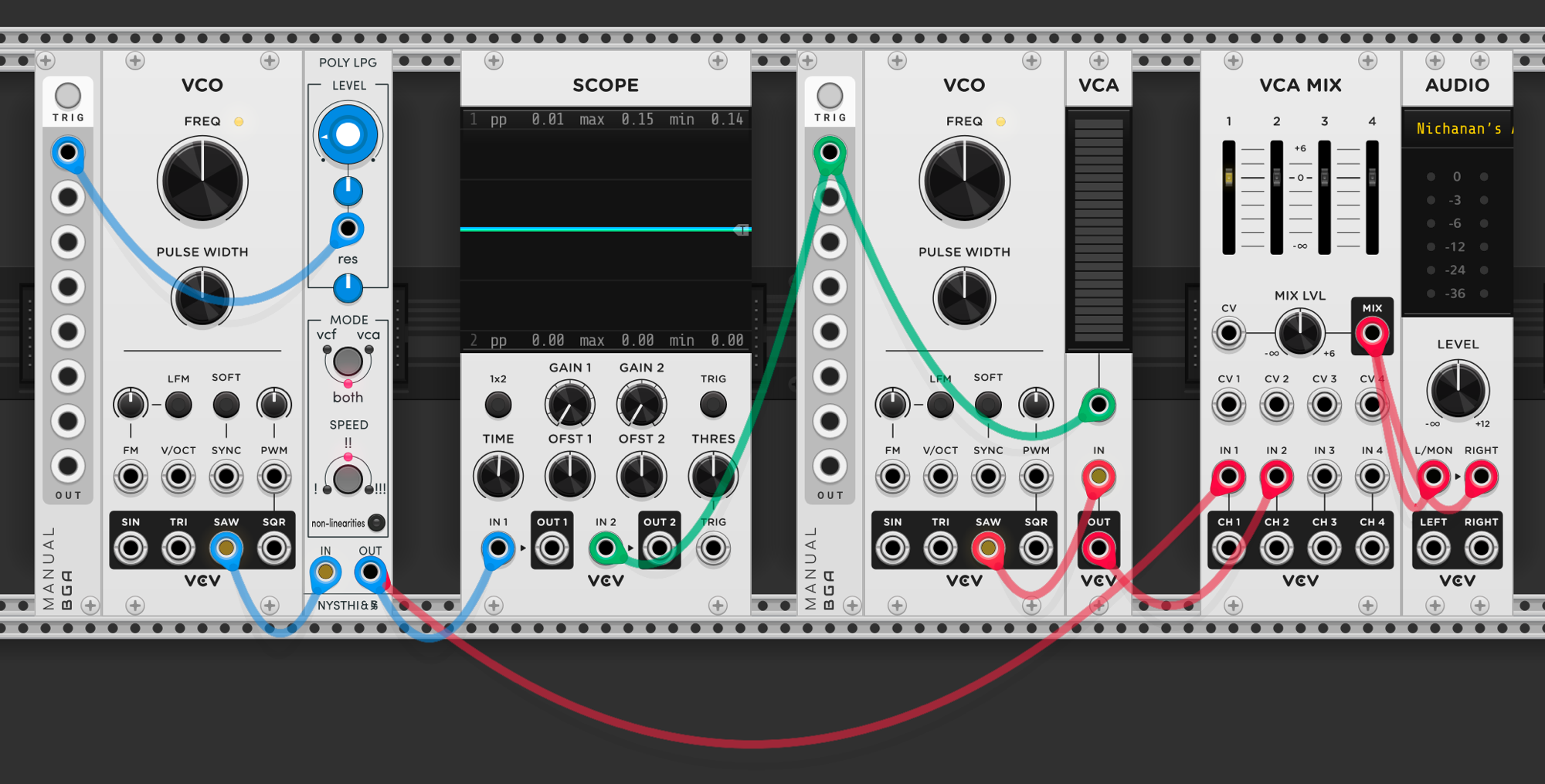
Comparison patch: two VCOs playing the same sawtooth wave. The left VCO goes through a Poly LPG (by NYSTHI) set to “both” mode, the right goes through a standard VCA. The scope shows both signals — the LPG path lets you hear how the sound darkens as it decays, while the VCA path only gets quieter. The LPG module has a decay time control that sets how long the vactrol takes to close after being triggered.
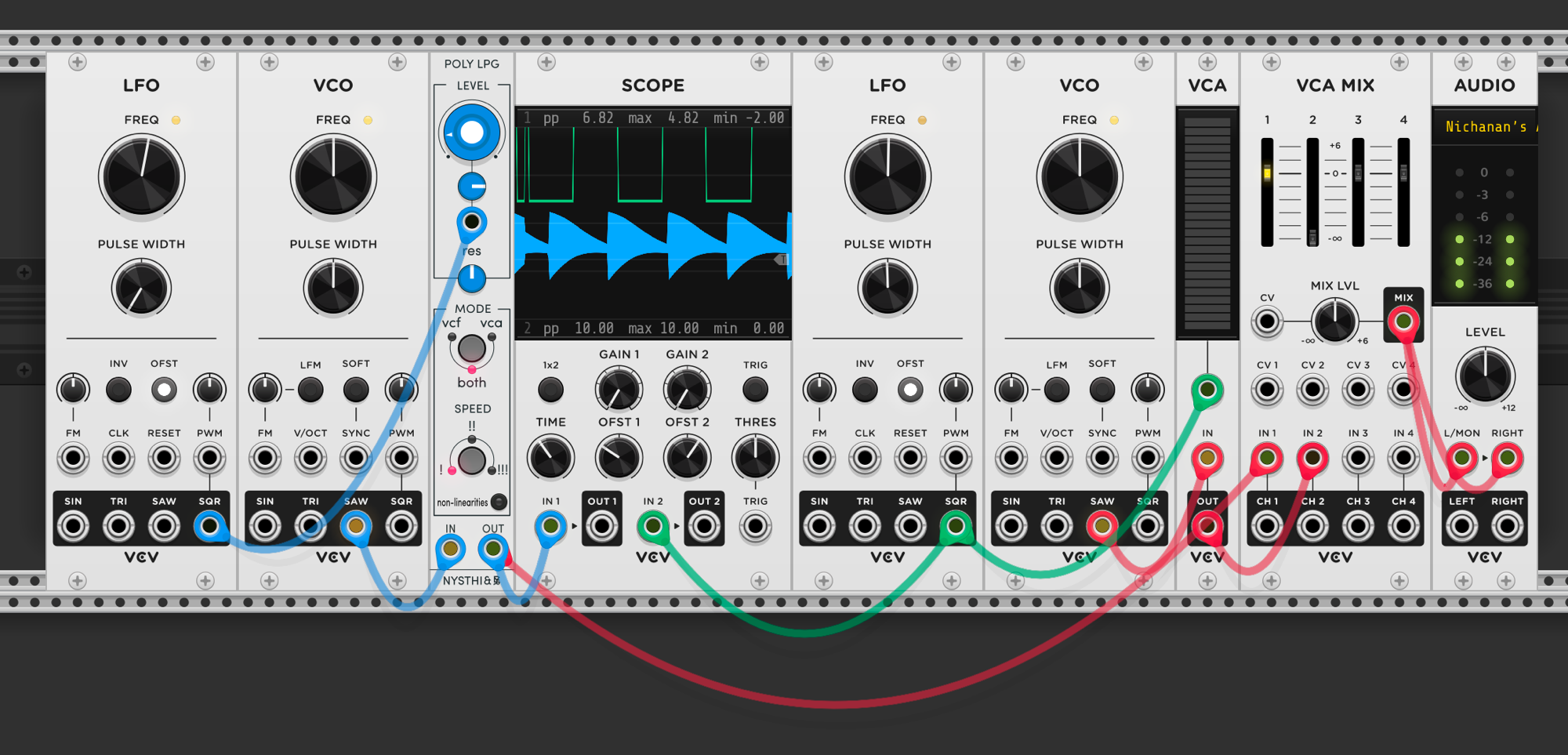
The scope makes the difference visible. The top trace shows the LPG output — each burst of sound decays in both volume and brightness, with the waveform shrinking and softening over time. The bottom trace shows the VCA path — the square wave maintains its full amplitude whenever the gate is open, with hard on/off transitions and no shaping of the tone. The LPG’s vactrol decay gives each note a natural fade that a simple gate can’t produce.
The LFO’s pulse width controls how long each gate stays high — adjusting it changes the duration of each sound burst before the LPG closes. A narrow pulse width gives short, clipped hits; a wider pulse holds the LPG open longer.
Different signals can open the LPG, not just square waves. Any CV that rises and falls will work — the shape of the opening signal determines the character of the sound.
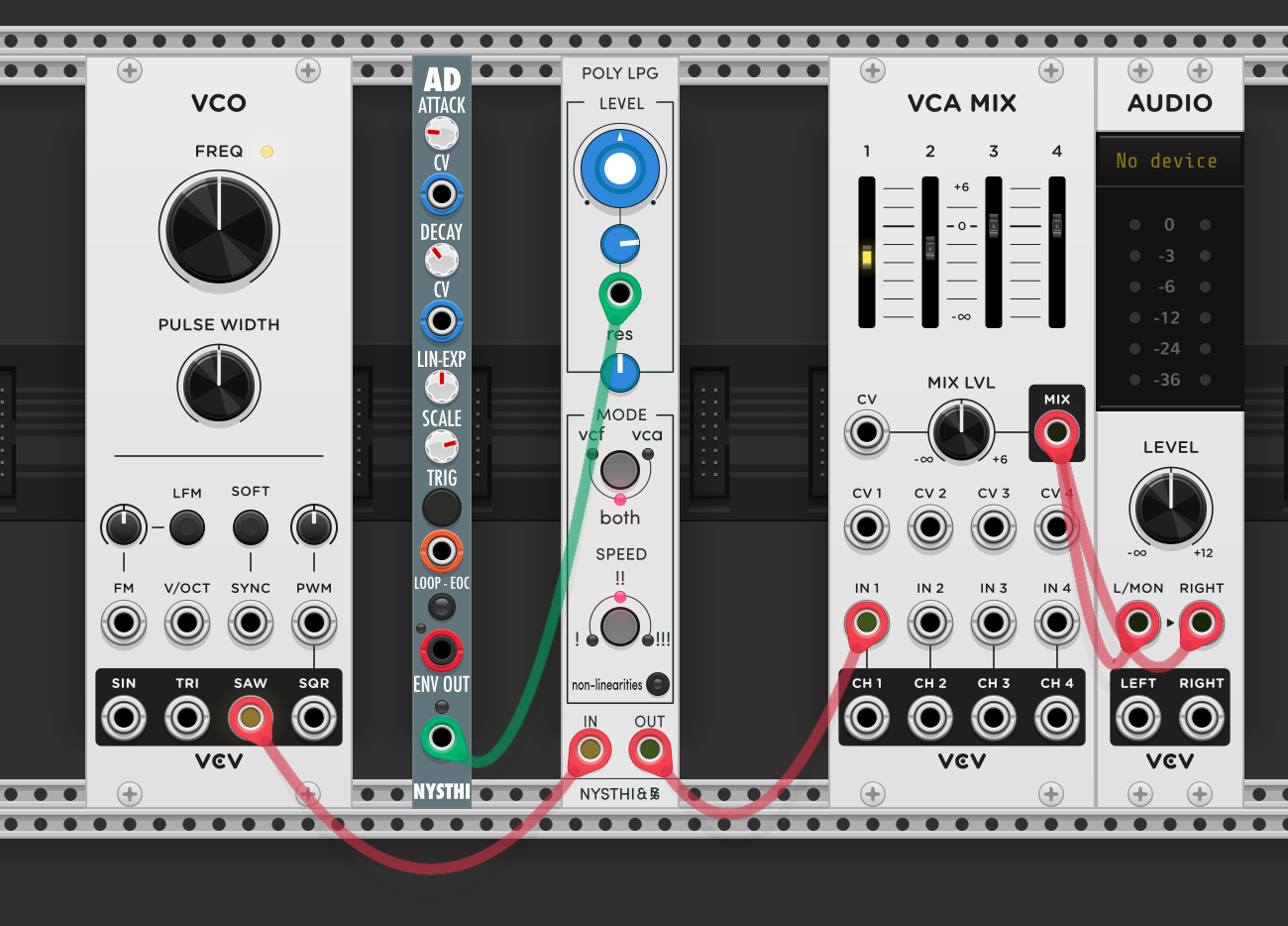
AD envelope driving the LPG: replacing the LFO with an attack/decay envelope gives direct control over how the LPG opens and closes. The attack knob controls how quickly the LPG opens (how fast the sound reaches full brightness and volume), and the decay knob controls how long it takes to close back down. A fast attack with a medium decay produces a pluck-like response — bright initial strike that fades naturally. A slower attack softens the onset, making it more pad-like. The envelope shape interacts with the vactrol’s own response, so the result is a blend of both — the envelope provides the intentional shape, the vactrol adds its organic character on top.
Pinging filters
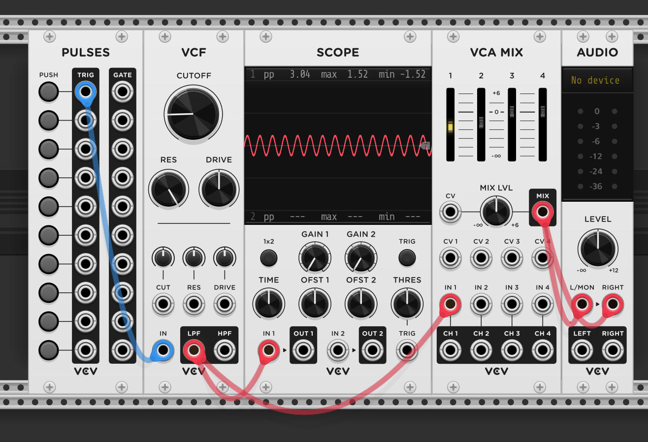
With resonance cranked all the way up, the filter self-oscillates — producing a sine wave at its cutoff frequency with no input signal. The scope shows a clean sine wave from the VCF’s LPF output. The cutoff knob controls the pitch. No VCO needed — the filter is the oscillator.
Pinging the filter: with resonance turned back down below self-oscillation, the filter no longer sustains a tone on its own. But sending a short trigger pulse into the filter’s input excites it — the filter rings briefly at its cutoff frequency, then the oscillation decays naturally. The scope shows the result: a short percussive burst that dies away quickly. This is a “ping” — the trigger hits the filter like striking a bell, and the resonance determines how long it rings. The cutoff frequency sets the pitch of the ping. No oscillator, no envelope — just a trigger and a resonant filter producing a complete percussive voice.
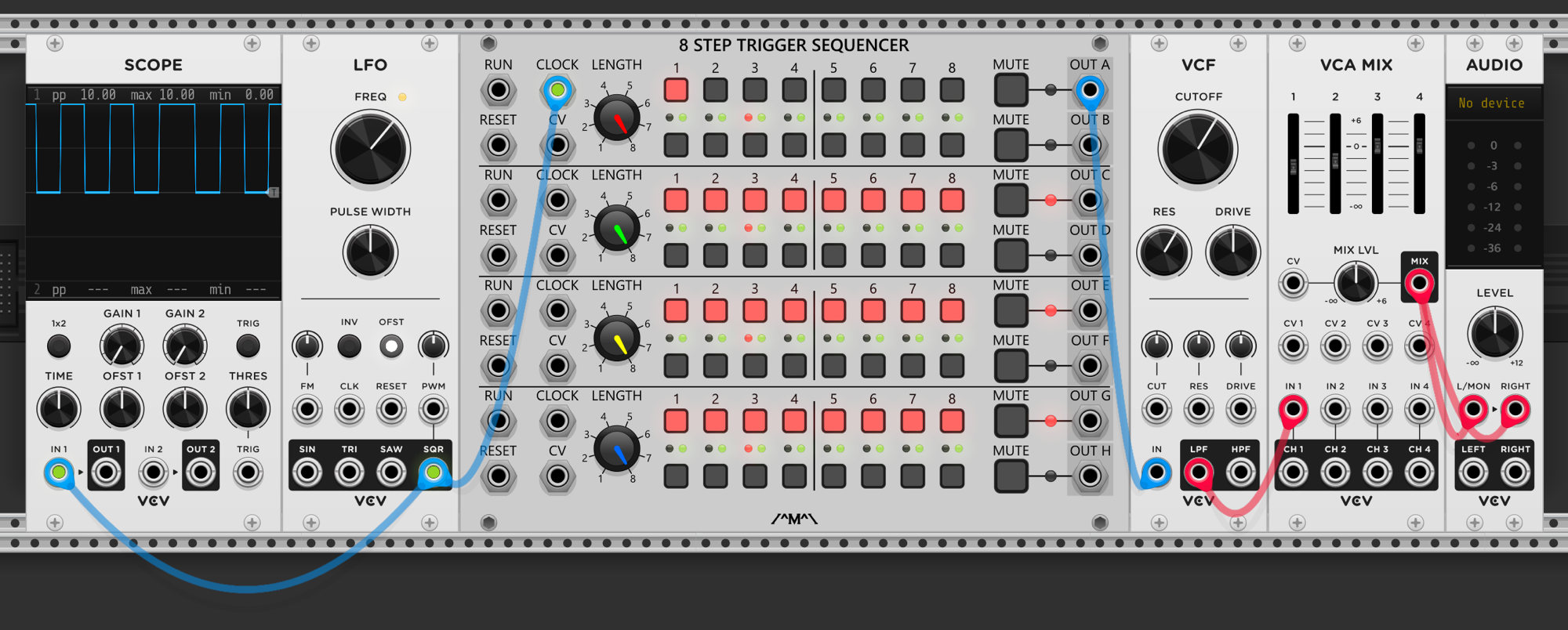
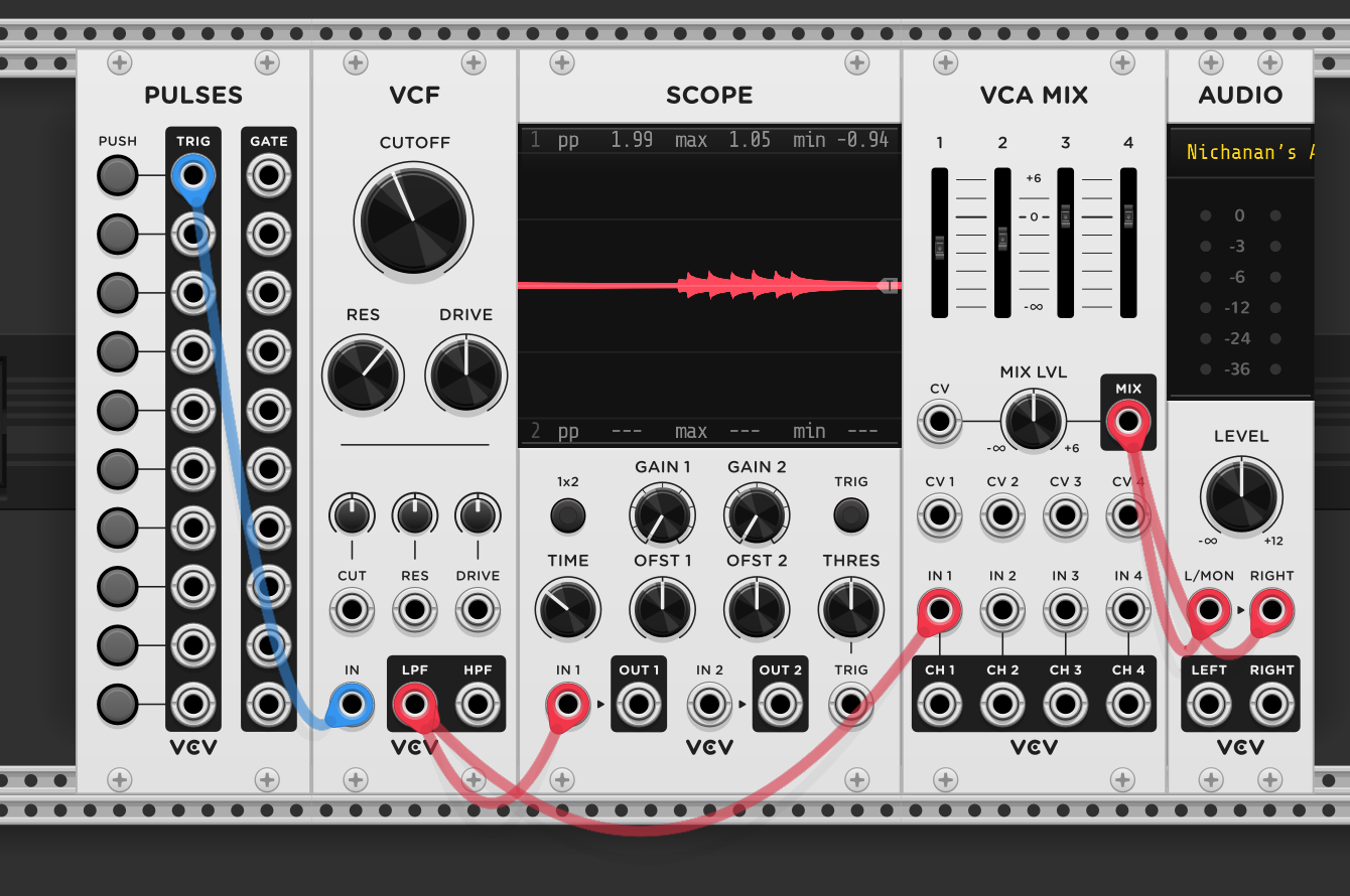
Gate vs trigger for pinging: an LFO clocks a trigger sequencer with one step active. The sequencer’s output goes into the VCF, but the scope shows two clicks per step instead of one. This happens because a gate signal has two sharp transitions — the rising edge (gate opens) and the falling edge (gate closes) — and both excite the filter. Each edge is a sudden voltage change that rings the filter independently.
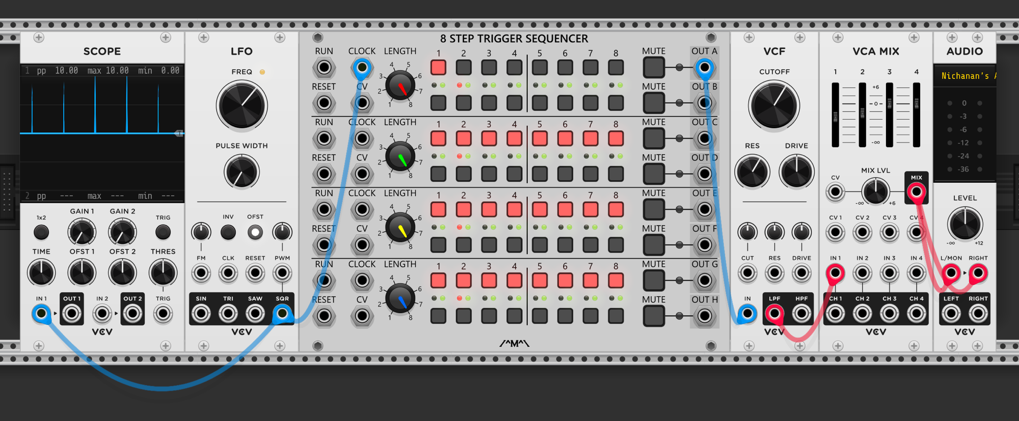
The fix is narrowing the LFO’s pulse width to shorten the gate duration. With a very narrow pulse, the rising and falling edges happen so close together that the filter treats them as a single impulse — one clean ping per step instead of two. This is the difference between a gate (sustained high voltage) and a trigger (brief spike): pinging filters needs triggers, not gates. If your clock source outputs gates, narrowing the pulse width converts them into trigger-like signals.
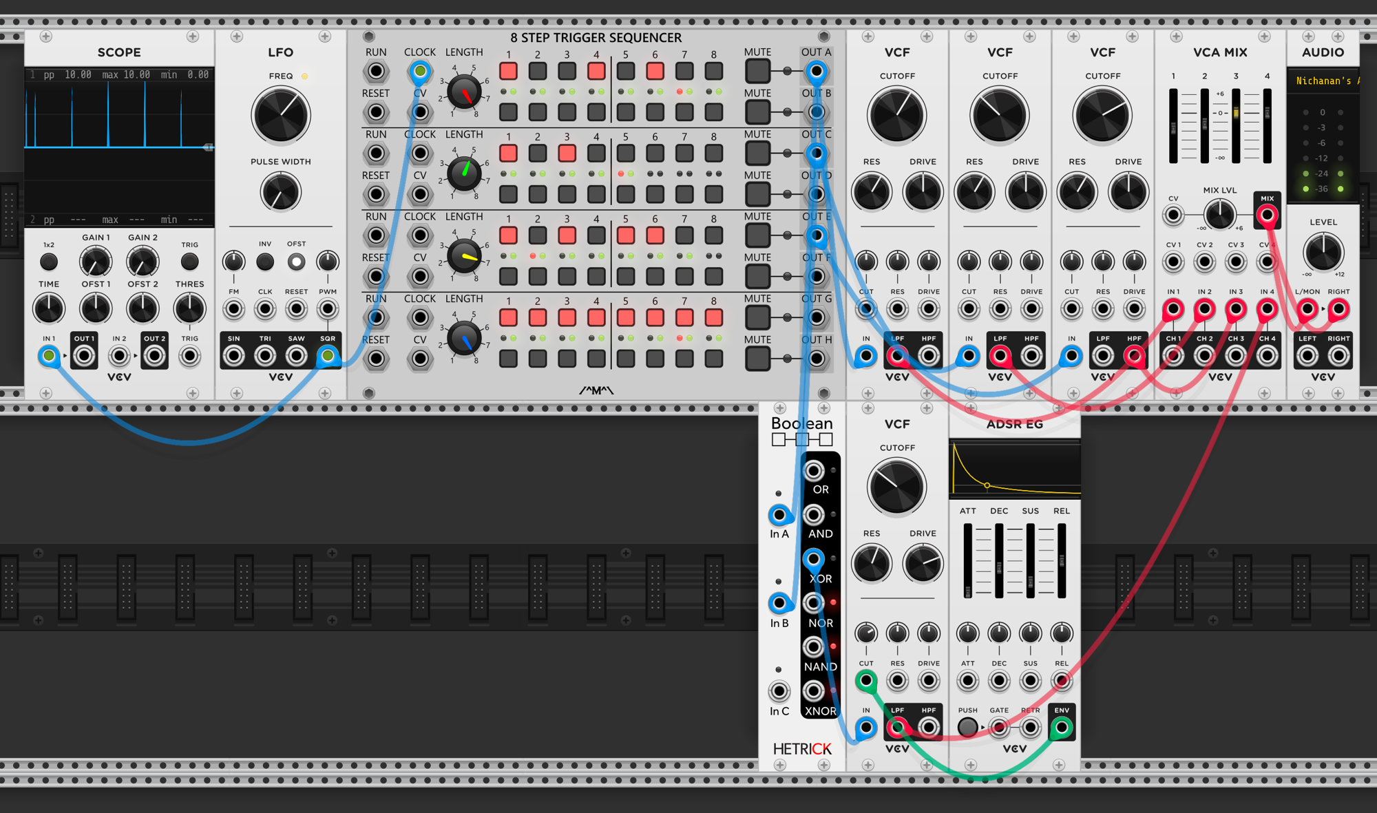
Four-voice percussion from pinged filters: the trigger sequencer’s four rows each program a different rhythmic pattern, and each row triggers a separate VCF. Every filter has its own cutoff and resonance settings, so each produces a different pitched ping — one low and thuddy, another mid-range, another high and clicking. The four LPF outputs go to separate channels on VCA MIX. On the bottom row, a Boolean logic module combines two of the trigger rows, and the result feeds a fourth VCF with an ADSR EG shaping its response. A full percussion kit — kick, toms, clicks — built entirely from pinged filters, with no oscillators anywhere in the patch.