Envelope Follower & Side-Chaining
Mixers
A mixer sums multiple signals into one output. In modular, this goes beyond combining audio voices for a final mix — you can mix any CV signals together to create compound modulation shapes that no single module could produce on its own.
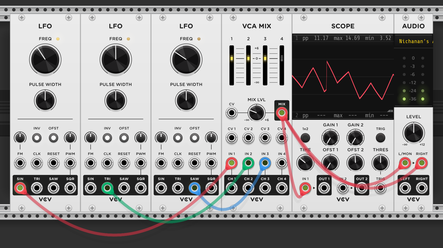
Three LFOs, each set to a different frequency and waveshape — sine, triangle, and sawtooth — summed through VCA MIX. The scope shows the combined result: a complex waveform that doesn’t repeat on any simple cycle. Each LFO contributes its own shape and timing, so the sum moves in ways none of them do individually. Routed to a filter cutoff or VCA level, this would produce modulation that feels organic and evolving rather than cyclical.
The same principle works at audio rate. Mixing two or more oscillators before any filtering creates a combined waveshape with a richer harmonic spectrum than any single waveform — this is the basis of additive-style sound design, building complexity by layering simple signals.
Mixers come in two types — AC-coupled (filter out DC/low-frequency, audio only) and DC-coupled (handle both audio and CV, session 13 covers AC vs DC coupling in detail). DC-coupled mixers are more versatile since they can sum control voltages as well as audio signals. In cascade mixers, each channel’s output is normalled to the next channel’s input. Taking an output from an intermediate channel creates a sub-mix of only the channels above it — useful for creating separate headphone or effects mixes without an additional mixer.
Matrix mixer
A matrix mixer has multiple inputs and multiple outputs, with a knob at every intersection controlling how much of each input reaches each output. Where a standard mixer funnels everything into one sum, a matrix mixer produces several different sums simultaneously — each output gets its own blend of the inputs.
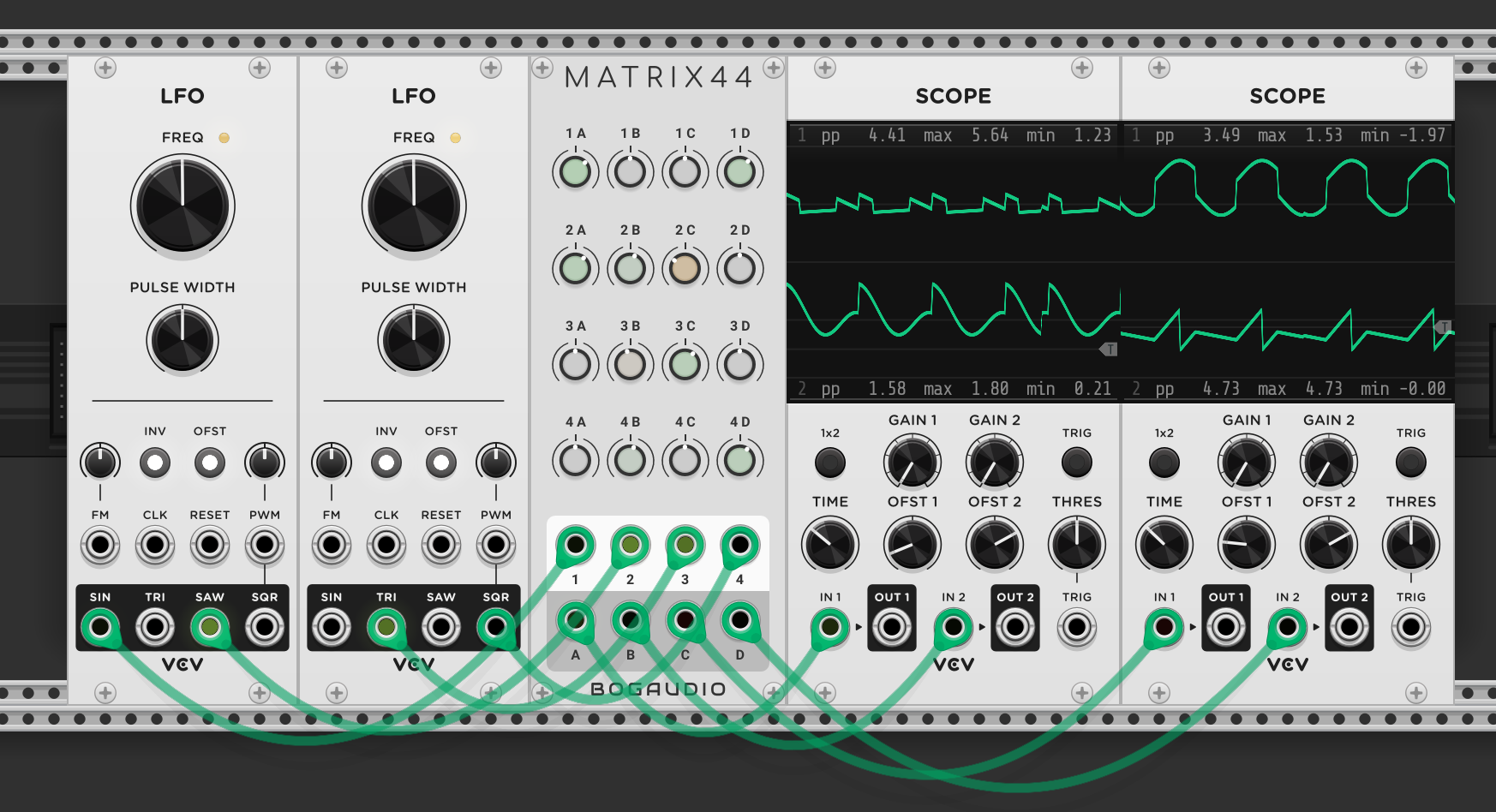
Two LFOs provide four waveshapes across the matrix mixer’s four inputs. The MATRIX44 (Bogaudio) has a 4x4 grid of knobs — row 1 controls how much of input 1 reaches outputs A through D, row 2 controls input 2, and so on. Each column’s knobs determine the recipe for that output. The scopes show the results: output A gets one combination of the four waveshapes, output B gets a different combination, and so on. By adjusting the knob levels, each output becomes a unique blend — four distinct modulation signals derived from the same two LFOs. This is powerful for creating related-but-different modulation across multiple parameters from a small number of sources.
Feedback loops with a matrix mixer
A matrix mixer’s multiple inputs and outputs make it a natural place to build feedback loops — route an output back through a processor and into another input, so the signal feeds on itself.
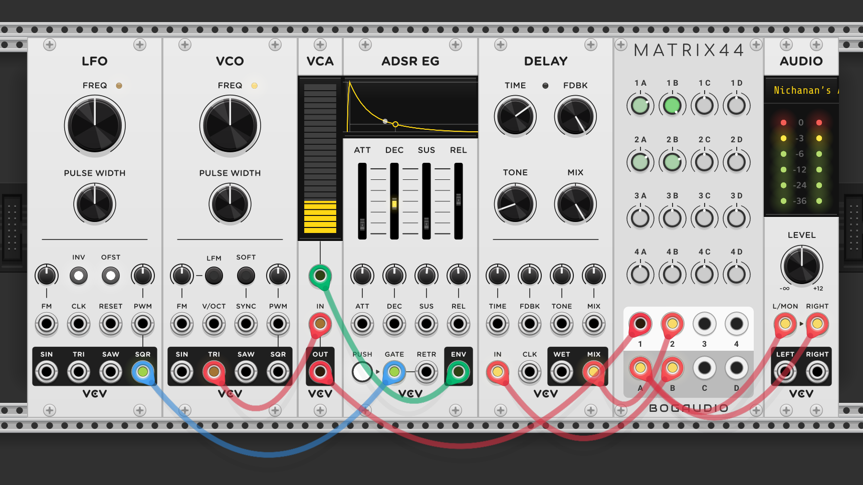
The voice (VCO through VCA, shaped by an ADSR) enters matrix input 1. Output B feeds into a delay module, and the delay’s wet signal returns to matrix input 2 — completing the loop. Output A goes to audio. Turning up knob 1A sends the dry voice to the output. Turning up 1B sends the voice into the delay. Turning up 2A brings the delayed signal to the output alongside the dry voice. Turning up 2B is where it gets interesting — that sends the delay’s output back into the delay again, creating feedback. The matrix knobs become precise controls over how much signal recirculates, making it easy to dial in anything from a subtle echo to a runaway feedback wash.
The same technique works with filters — sending a filter’s output back into its own input through the matrix mixer creates unique waveshaping, distinct from standard resonance.
Delay parameters:
- Time — the gap between the original sound and its echo. Short times (under ~50ms) blur into a comb-filter effect — metallic, hollow coloring rather than a distinct echo. Medium times give a clear rhythmic repeat. Long times create wide spacious echoes.
- Feedback (FDBK) — how much of the delayed signal feeds back into the delay input. At zero, you get a single echo. Turning it up adds repeating echoes that decay over time — each repeat quieter than the last. High feedback produces long trails of decaying repeats. Past a certain point, the echoes stop decaying and sustain or even build, heading toward self-oscillation.
- Tone — a filter on the delayed signal. Turning it down darkens each repeat, so successive echoes lose high-frequency content — mimicking how echoes sound in physical spaces, where air absorbs treble. Turning it up keeps the repeats bright and present.
- Mix (dry/wet) — the balance between the original signal and the delayed signal. Fully dry means no effect. Fully wet means only the echoes, no original sound. In a feedback loop through a matrix mixer, the mix knob interacts with the matrix’s own level controls, so setting it fully wet and controlling the blend at the matrix gives the most precise control.
Envelope follower
An envelope follower tracks the amplitude of an incoming signal and outputs a smooth CV that represents its volume over time. It extracts the shape of a sound’s loudness — ignoring the actual waveform and just following how loud or quiet it is moment to moment.
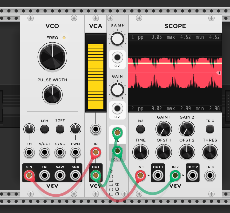
A VCO sine wave goes through a VCA, and the VCA output feeds both the scope (channel 1, red) and a Bogaudio FOLLOW module. The follower’s output goes to scope channel 2 (green). As the VCA volume is adjusted up and down by hand, the top trace shows the audio waveform growing and shrinking, while the bottom trace shows the follower producing a smooth CV that tracks the amplitude contour. The follower doesn’t care about the pitch or waveshape — it just measures how loud the signal is and outputs a corresponding voltage.
The damp knob controls how sensitive the follower is. At low settings, the output responds quickly and closely tracks rapid volume changes. Turning damp up smooths the response — the follower reacts more slowly, rounding off sudden spikes and dips. Higher damping gives a gentler, more averaged-out CV; lower damping gives a twitchier, more reactive one.
Beyond ducking, the envelope follower captures performance dynamics from any audio source — a guitar, drum loop, or field recording through the follower maps its loudness contour as CV, which can then control filter cutoff, LFO speed, or any other parameter for audio-reactive modulation.
Ducking and side-chaining
Side-chaining uses the envelope follower to make one sound respond to another — the classic example is a kick drum pushing a pad or bass down every time it hits, so the kick punches through the mix.
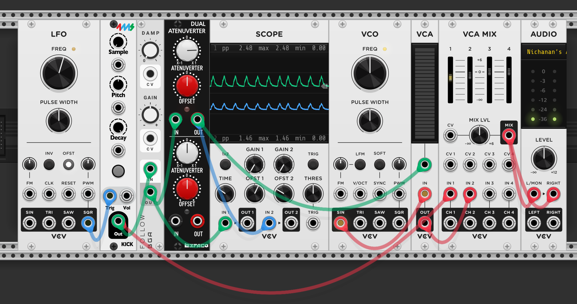
The setup: an LFO triggers a kick drum, and a VCO produces a continuous sine wave through a VCA — both mixed together through VCA MIX to audio. The kick’s audio is also routed through the envelope follower, which tracks its amplitude. The follower’s output goes through a dual attenuverter, which will be used to invert and offset the signal — turning a positive “kick is loud” CV into a negative “turn the sine down” CV that can control the sine’s VCA.
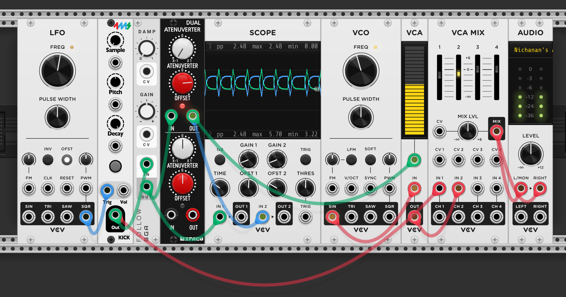
With the attenuverter’s offset turned up, the ducking effect kicks in. The follower detects each kick hit, the attenuverter inverts that CV so louder kick = lower voltage, and that inverted signal controls the sine’s VCA. The scope shows the result: the sine wave’s amplitude dips every time the kick fires, then swells back up as the kick decays. The kick pushes the sine out of the way, making space in the mix — sound responding to sound, no manual automation needed.
A simpler ducking approach without the envelope follower: invert an envelope with an attenuverter and use offset to push the resting level to maximum. When the gate fires, the inverted envelope pulls the level down then returns — instant ducking from any trigger source, no audio input needed.
Sequencing modulation with VCAs
A VCA doesn’t just control volume — it controls whether a signal passes through at all. By using a sequencer row to open and close a VCA, you can decide on which steps a modulation or effect is active. The VCA becomes a gate for any signal, not just audio.
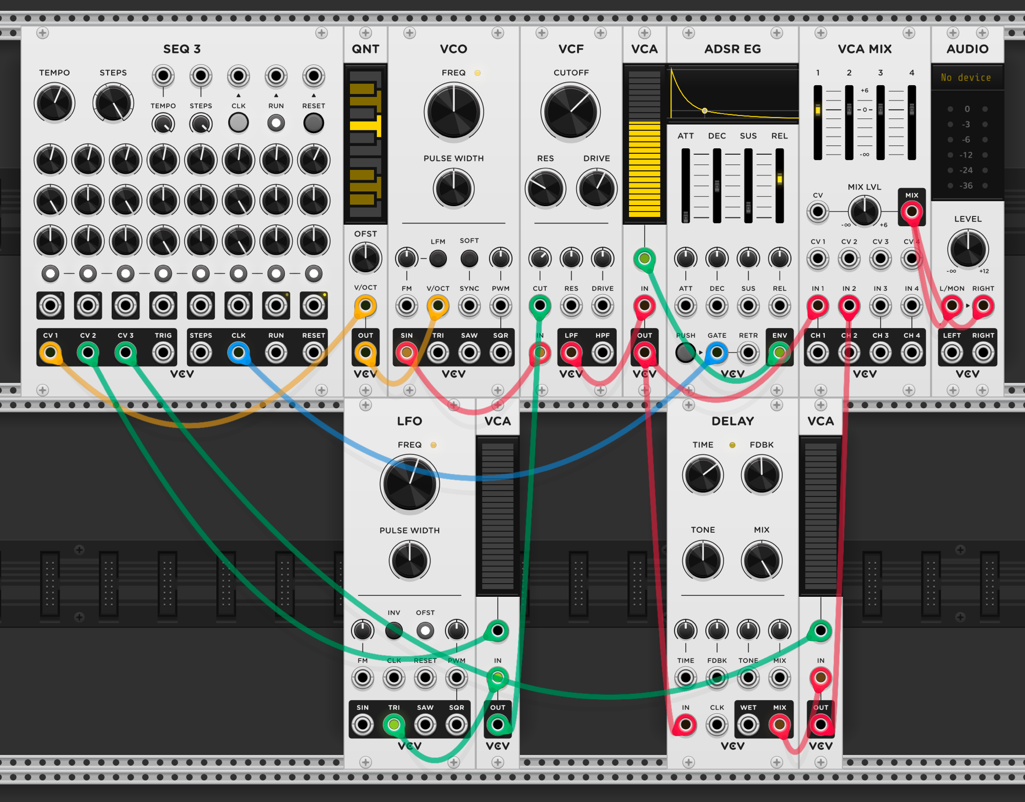
The main voice is a standard subtractive patch: SEQ3 row 1 sequences pitch through a quantizer into a VCO, through a VCF and VCA shaped by an ADSR, into VCA MIX channel 1. The interesting part is how two other sequencer rows control when modulation and effects happen. An LFO modulates the filter cutoff, but instead of running constantly, the LFO signal passes through a VCA that’s opened only on steps 1, 3, and 6 by SEQ3’s second row — on all other steps, the VCA is closed and the LFO has no effect on the filter. Similarly, the voice audio feeds a delay module, but the delay’s wet output passes through another VCA controlled by SEQ3’s third row, active only on steps 4 and 6 — so the delay effect only appears in the mix on those specific steps. The sequencer isn’t just choosing notes — it’s choreographing which modulations and effects are present at each moment.
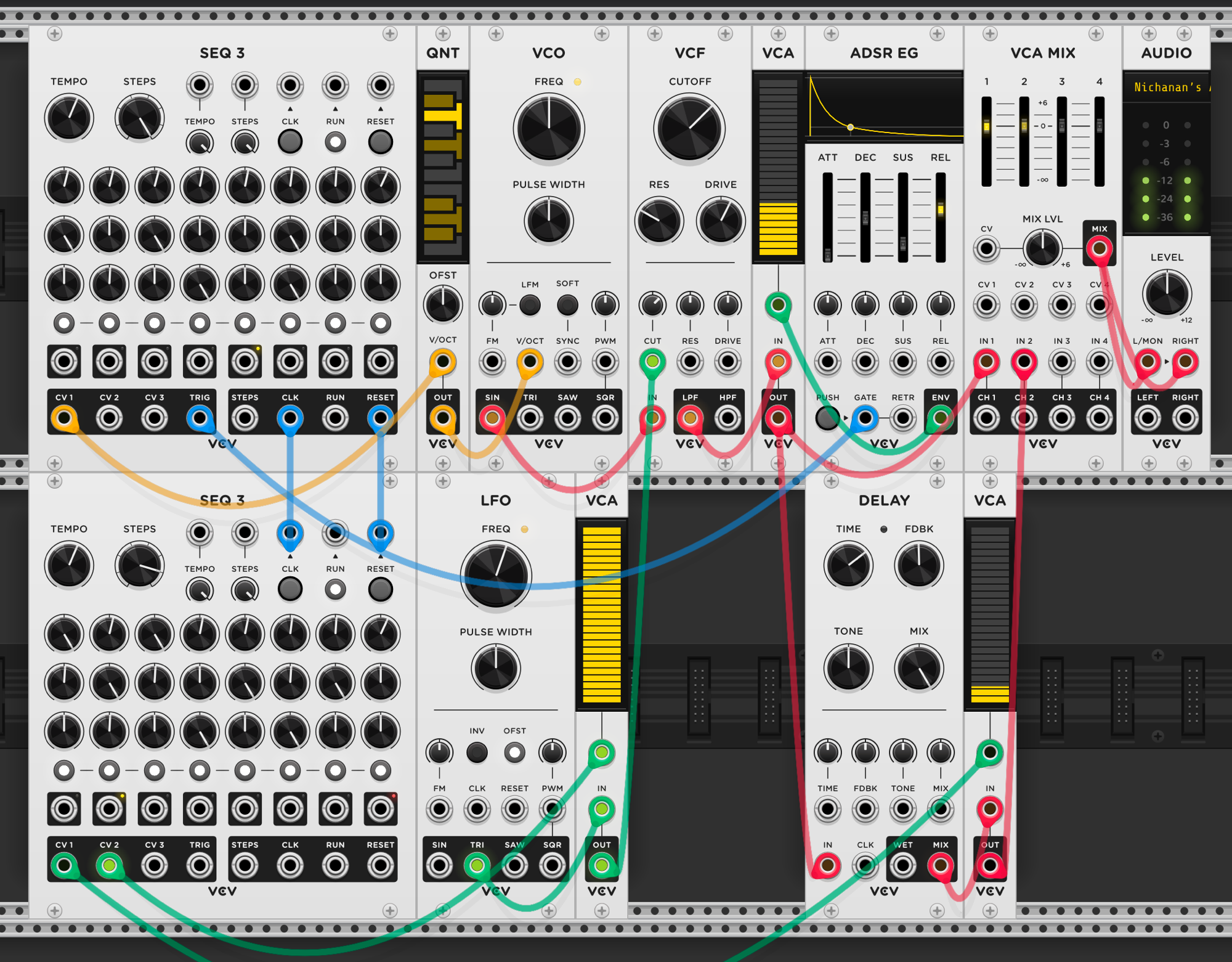
Taking it further: a second SEQ3 is added specifically to control the modulation and delay VCAs, freeing up the first sequencer’s rows for other uses. The two sequencers share the same clock and reset, so they step together — but the second SEQ3 is set to 7 steps while the first has 8. Because the modulation sequencer is one step shorter, its pattern drifts against the note pattern by one step each cycle. On the first pass, the filter modulation might land on notes 1, 3, and 6. On the next pass, it shifts to notes 8, 2, and 5 — and so on. The two patterns only realign after 56 steps (8 × 7), creating a long evolving cycle from two short sequences. This is the same polyrhythmic principle from session 11 — mismatched loop lengths generating variation — but applied to modulation routing instead of rhythm.
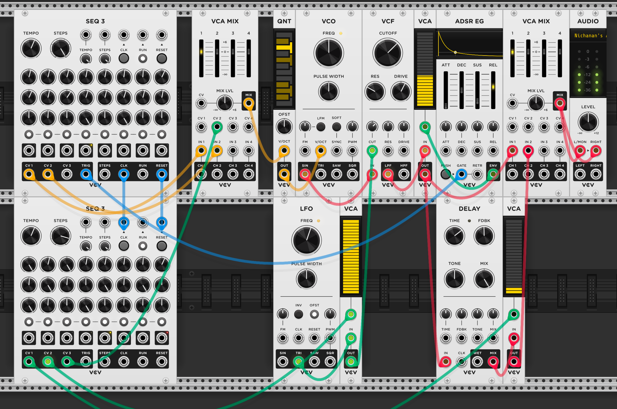
Adding a mixer between the sequencer and quantizer creates pitch variation from two combined sequences. SEQ3 row 1 provides the base melody through VCA MIX channel 1 — always present. Row 2 provides a second pitch sequence through channel 2, but its amplitude is controlled by the second SEQ3’s third row. On steps where the second sequencer opens channel 2, the two pitch CVs are summed before hitting the quantizer — the note shifts by whatever row 2 contributes. On steps where channel 2 is closed, only row 1’s pitch comes through. Because the second sequencer has 7 steps against the first’s 8, which steps get the pitch offset drifts each cycle. The base melody stays recognizable, but the harmonic variations shift around it in a long, non-repeating pattern.
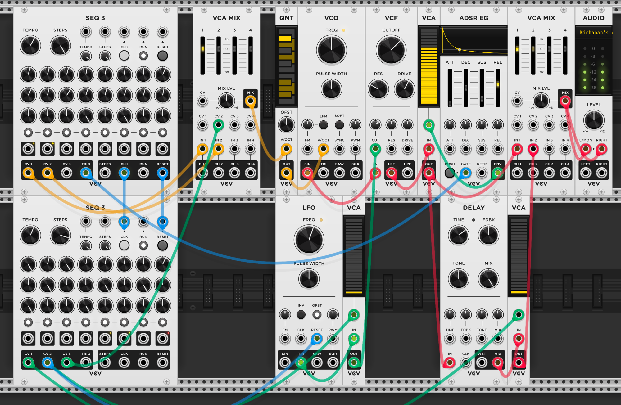
A finishing touch: the second sequencer’s CV2 output — the same signal that opens the filter modulation VCA — also resets the LFO. Without this, the LFO is free-running, so the filter sweep starts at whatever phase the LFO happens to be at when the VCA opens. The modulation effect would sound different each time — sometimes starting mid-sweep, sometimes at a peak. By resetting the LFO to zero each time the modulation activates, the filter sweep always starts from the same point, giving a consistent, repeatable effect on every step where the modulation is active.
Reflection
Phase 4 shifted how I think about what modules are for. The LPG stands out — coupling volume and brightness decay replicates how acoustic instruments actually behave, and that’s the effect I’ve been missing. Notes so far have felt discrete and atomic; glide from session 13 breaks that by letting pitch flow between steps instead of jumping. And the trigger sequencer keeps proving useful — four rows of rhythmic patterns driving pinged filters in session 14 gave a full percussion kit with no oscillators, and here in session 15 the same approach choreographs when modulation and effects appear. The common thread: these aren’t new sound sources, they’re new ways to shape how and when sound moves. The comparator and boolean logic modules from session 10 and session 12 fit the same pattern — comparators split a sequence across voices by voltage threshold (high notes here, low notes there), and boolean logic derives new rhythms from existing gate patterns (AND, OR, XOR). Both extract more behavior from fewer sources.
I’ve started listening to techno differently — when I hear a sound, I try to name the effect and map it to modules. A decaying hit becomes “envelope into VCA,” a wash of space becomes “reverb with high feedback,” a shifting timbre becomes “LFO modulating filter cutoff.” It’s like learning to read a language I was only hearing before — the music becomes legible as signal flow, not just sound.