Generative Rhythm
Comparator-based generative gates
A Comparator converts a continuous signal into gates by comparing it against a threshold — another way to derive gate patterns from CV, alongside the boolean logic approach of combining existing gates.
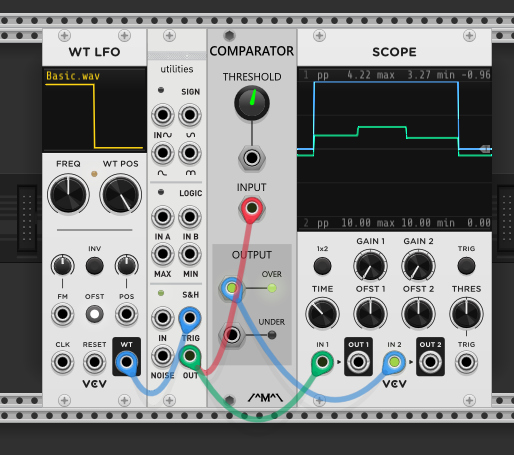
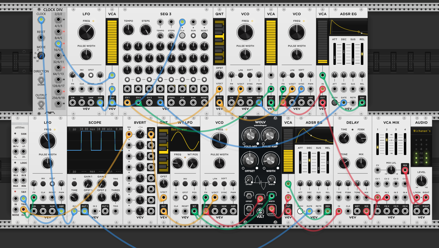
A WT LFO triggers the S&H module, which samples noise on each trigger. Each random voltage feeds the Comparator’s input.
The Comparator has a threshold knob. It compares the incoming signal against that threshold and has two outputs:
- OVER — outputs a high gate whenever the input is above the threshold
- UNDER — outputs a high gate whenever the input is below the threshold
The scope shows the OVER output: the gate stays high for as long as the sampled voltage remains above the threshold, then drops when the next sample lands below it. Because each S&H sample is random, the gate lengths are unpredictable — sometimes a long sustained gate, sometimes a short blip. This creates a rhythmically irregular gate pattern from a steady clock, which is the generative part: the when is regular (LFO trigger rate), but the whether each step produces a gate depends on where the random voltage lands relative to the threshold. Turning the threshold up means fewer gates pass (only the highest random values clear it); turning it down means more gates pass.
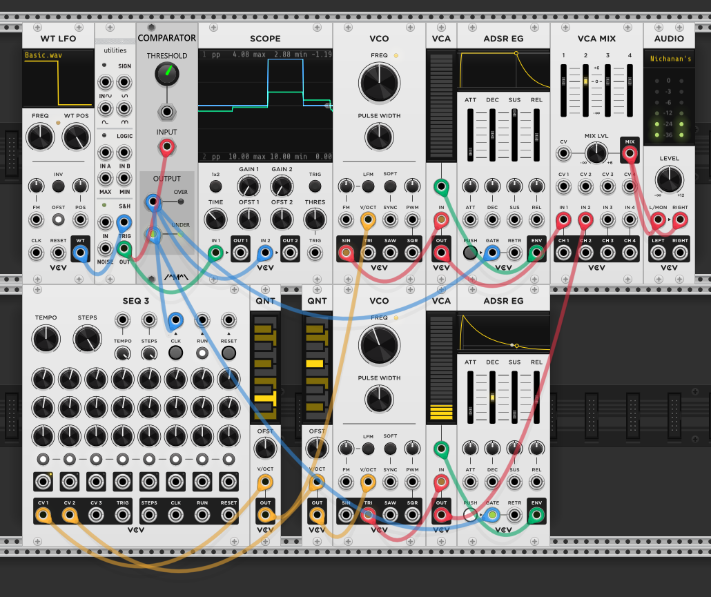
The Comparator’s OVER output is patched to two different destinations: the pitch (V/OCT) of one voice and a modulation input on the other. When the gate goes high, one voice shifts pitch while the other’s timbre changes — but because it’s the same gate signal driving both, the timing of those changes is linked while the musical effect is completely different on each voice. The pitch jumps happen at the same moments as the timbral shifts, but they pull the voices apart perceptually — one changes what note it plays, the other changes how it sounds. The result is two voices that share a generative rhythm but drift in and out of musical alignment.
To bring the voices back into sync, a second S&H (the Kinks module, bottom row) is inserted in the second voice’s pitch path. The Comparator’s UNDER output triggers this S&H. Now the second voice only updates its pitch when UNDER fires — the complementary moment to when OVER is active. Since OVER and UNDER are opposite (when one is high, the other is low), the two voices’ pitch changes are now locked to the same generative rhythm but on alternating beats: voice 1 changes on OVER, voice 2 changes on UNDER. They share a clock relationship again instead of drifting independently.
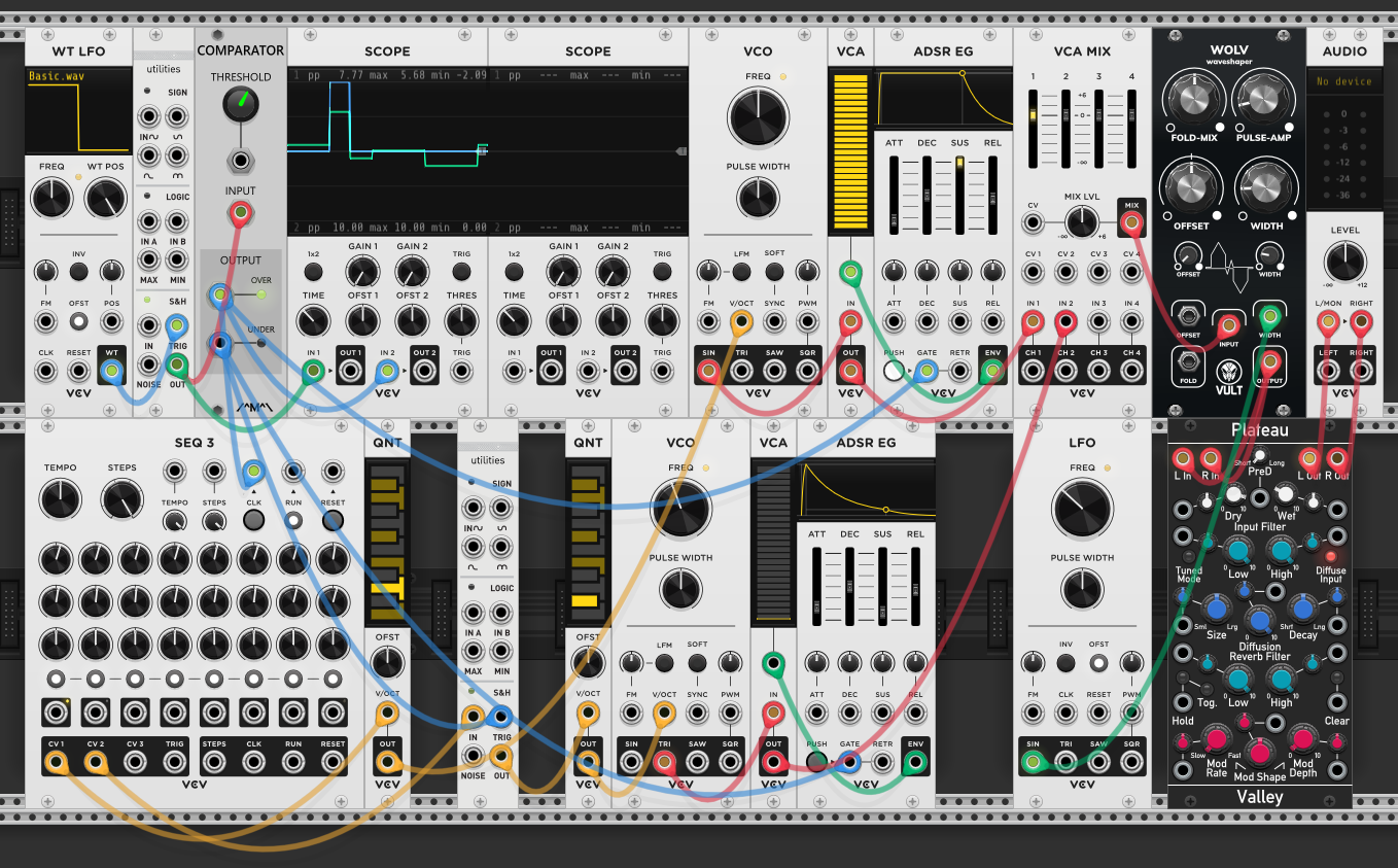
Adding effects to the Comparator patch: the mixed signal from VCA MIX passes through a WOLV waveshaper (by Vult) before hitting Plateau reverb and then Audio. The WOLV waveshaper adds harmonics and grit — the width parameter controls how aggressively it reshapes the signal. An LFO’s sine output modulates the width, so the amount of waveshaping sweeps continuously. The Plateau reverb smears the transitions — the reverb tail carries remnants of the distorted moments into the clean ones, blurring the boundary.
Another comparator technique: feeding an S&H’s output directly into a comparator produces gates of random length — the S&H voltage stays above or below the threshold for varying durations, and the threshold knob controls the probability (higher threshold = fewer but longer gates). At audio rate, a comparator turns smooth waveforms into harsh square-like pulses — a crude but effective form of distortion.
Beyond generative gates, the Comparator’s OVER/UNDER outputs can split any signal into two paths based on a threshold — useful for routing percussion and effects.
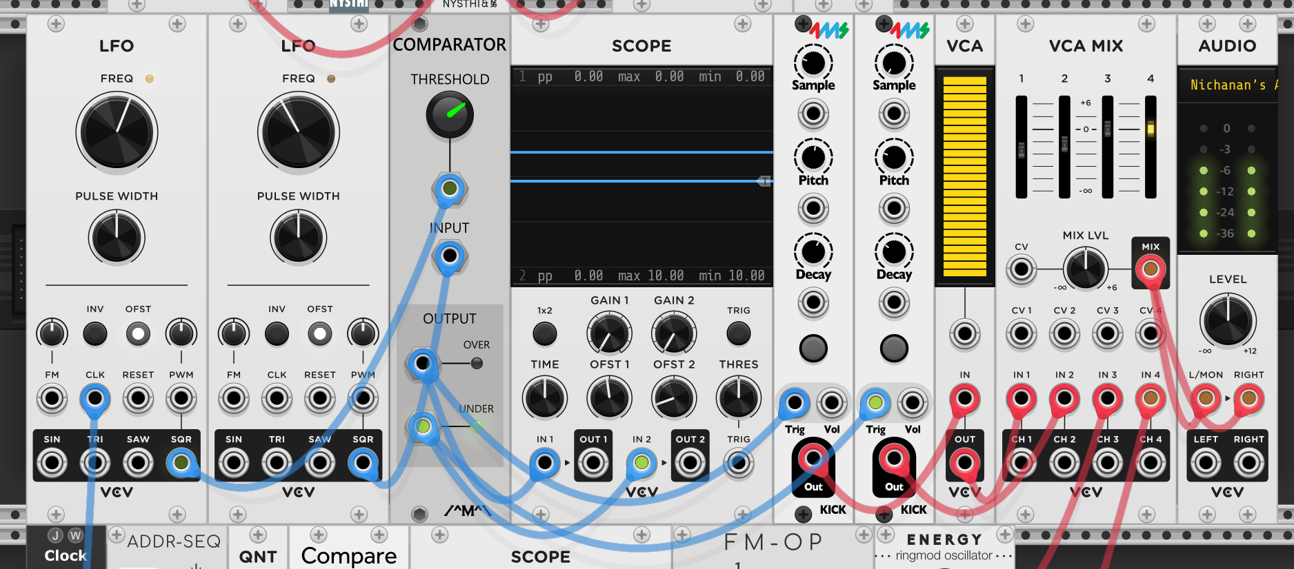
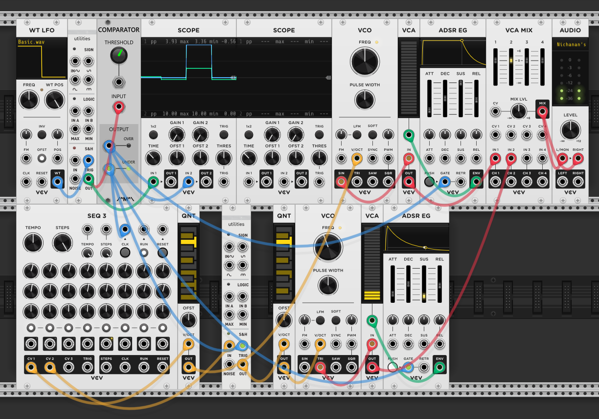
Splitting percussion with a comparator: two LFOs feed the Comparator — one as the input signal, the other compared against the threshold. The Comparator’s OVER output triggers one kick drum (FM-OP), and the UNDER output triggers a different kick with its own pitch and decay settings. The result is two distinct kick sounds alternating based on where the LFO crosses the threshold — higher notes trigger one kick, lower notes trigger the other. The threshold knob controls the split point, shifting the balance between the two sounds.
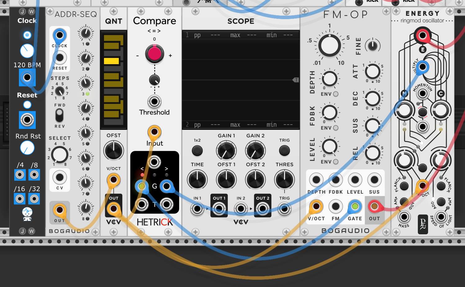
Pitch-dependent effects: a sequencer’s quantized pitch CV feeds the Comparator’s input. The threshold is set at a mid-range pitch — notes above the threshold trigger the OVER output, notes below trigger UNDER. Each output gates a different effect or voice: here the FM-OP voice plays on higher notes while the Energy ring mod oscillator plays on lower notes. The same sequence drives both, but the comparator splits it so different pitch ranges get different timbral treatment. Moving the threshold changes which notes cross into which effect — a simple way to make a single sequence sound more varied without adding complexity to the sequence itself.
Rampage as generative clock
The Comparator derives generative gates from random voltages — but the clock itself is still regular. A different approach: make the clock generative by using a function generator that controls its own timing.

A different approach to generative timing: Rampage with cycle enabled loops continuously — the rise and fall sliders control the ramp speed, making it behave like an LFO with independent control over the rising and falling portions. You need to hit the TRIGG button (or send a trigger to its input) to kick off the first cycle — it sits idle until then, even with cycle enabled.
The Rampage’s cycling envelope goes into the VCA, acting as a generative amplitude envelope. The VCA’s audio comes from the WT VCO, whose wavetable position is being modulated by the WT LFO — so the timbre continuously morphs as the LFO sweeps through the wavetable. The same LFO also modulates the VCF cutoff, so both the harmonic content of the oscillator and the filter brightness shift together. The Rampage controls when and how long the sound is heard (envelope shape), while the LFO controls what it sounds like (timbre and filtering).
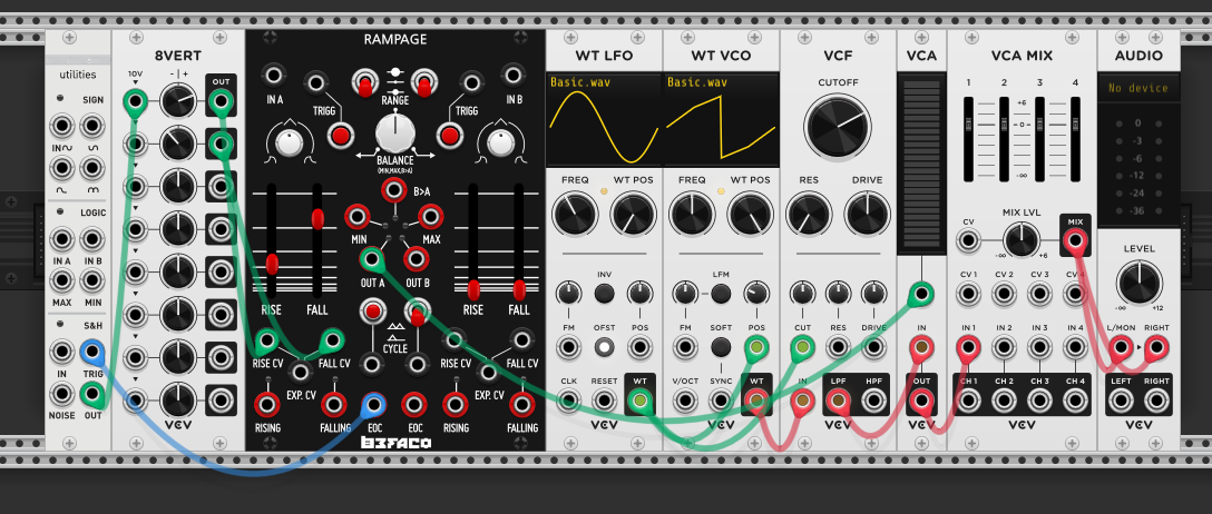
Adding pitch modulation: the 8VERT sends a static voltage through the Kinks S&H (triggered by Rampage’s cycle), and the S&H output goes through a quantizer before reaching the VCO’s V/OCT input. The quantizer snaps the sampled voltage to scale degrees, so each time the Rampage cycle triggers a new sample, the pitch jumps to a musically useful note rather than a random microtonal value. The 8VERT knob sets the range of voltages being sampled — turning it shifts the pitch region the S&H draws from.
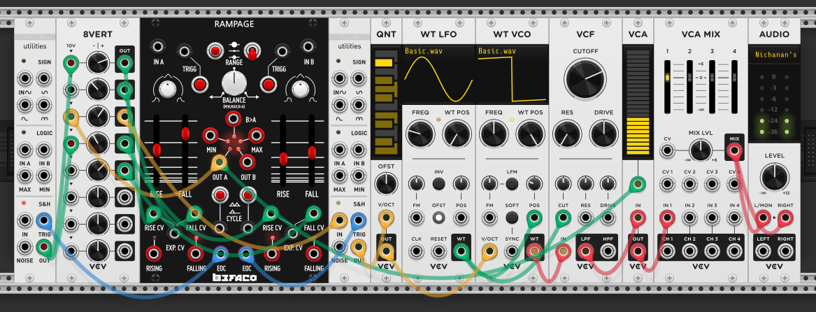
Rampage has two independent channels (A and B), each with their own rise/fall sliders and cycle toggle. Here the B channel’s end-of-cycle (EOC) output triggers a second S&H (another Kinks module), which samples a voltage and sends it through the quantizer to modulate pitch. Since A and B cycle at different rates (set by their respective rise/fall sliders), the pitch changes triggered by B’s EOC happen on a different schedule than the envelope from A. Two independent generative clocks from one module — the A side controls amplitude, the B side controls pitch, and they drift against each other. The result is voices fading in and out while pitches rise and fall on their own schedule — the interaction between the two cycles creates the generative movement.
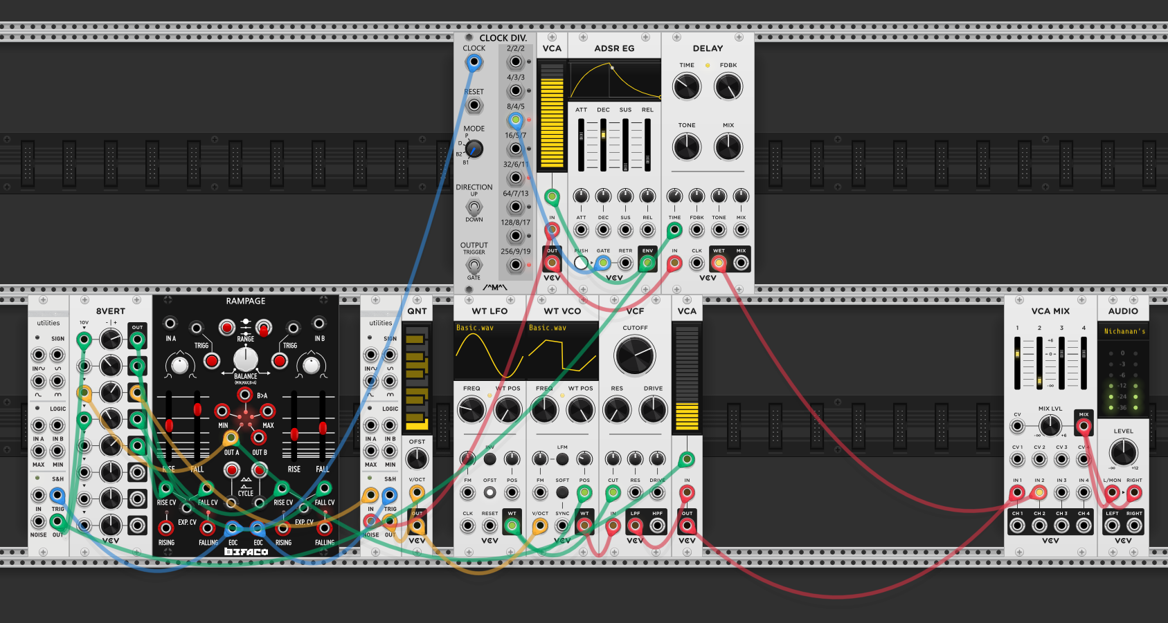
The second Kinks module has a noise output alongside its S&H. The B cycle’s EOC already triggers the S&H for pitch — now it also triggers an ADSR envelope that shapes the noise into percussive hits. The noise goes through a VCA controlled by this envelope, producing short bursts on each B cycle. That percussive signal passes through a Delay module before reaching the VCA MIX, adding rhythmic echoes. Since the B cycle rate is generative (drifting against A), the percussion hits land at irregular intervals — and the delay smears them further, filling the gaps between hits with fading echoes.
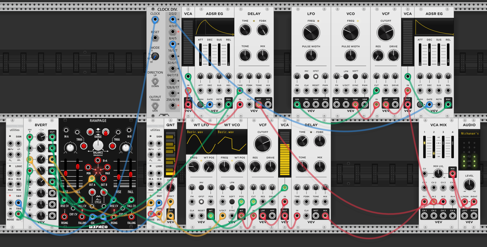
A third voice is added with the standard signal chain: LFO → VCO → VCF → VCA → ADSR EG, with its own Delay module. Three independent timing sources now overlap — Rampage A (envelope), Rampage B (pitch + percussion), and this LFO (third voice) — each drifting against the others. The VCA MIX brings all three voices plus the percussion together into the final output.
Probability
The Comparator and Rampage create generative timing — gates that fire unpredictably. Probability takes a different angle: the clock stays regular, but each beat has a chance of being heard. The rhythm is thinned rather than restructured. At audio rate, probability modules introduce glitch effects — feeding them oscillator output creates rhythmic dropouts and distortion, useful for chopped-up textures.
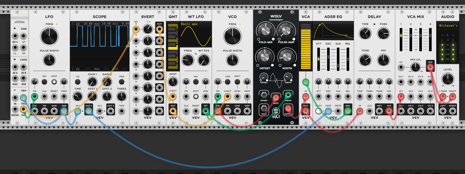
New patch — a single generative voice with several layers of modulation, each controlling a different aspect:
- Rhythm: the Kinks S&H output modulates the LFO’s frequency, so its square wave fires at changing rates. The square triggers the ADSR EG, which opens the VCA — controlling when and how often the voice sounds.
- Pitch: the 8VERT sends a voltage through a QNT (quantizer) to the VCO’s V/OCT input, setting the base pitch at scale-quantized values.
- Timbre: the VCO passes through the WOLV waveshaper before the VCA, adding harmonic distortion and wave folding to the raw oscillator.
- FM modulation: a WT LFO modulates the VCO’s FM input, adding continuous pitch movement on top of the quantized base note.
Signal path: VCO → WOLV → VCA (gated by ADSR) → Delay → VCA MIX → Audio.
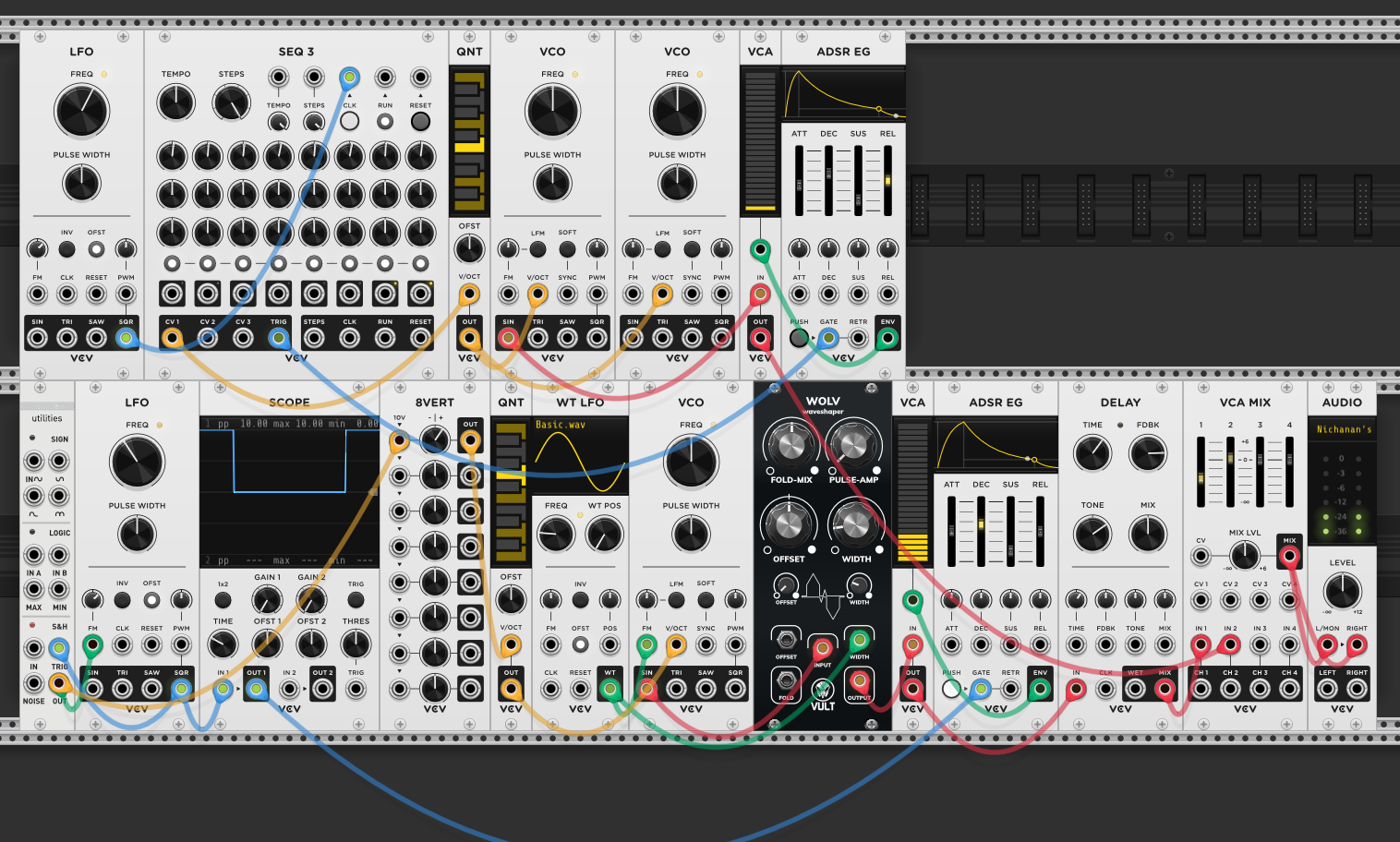
A second voice is layered on top: an LFO clocks a SEQ3 sequencer, whose CV output goes through a QNT into two VCOs playing the same quantized pitch. This voice runs at a different speed from the first — its LFO sets a steady clock rate while the first voice’s rhythm is generative (S&H-modulated). The contrast between a sequenced voice with predictable step patterns and a generative voice with irregular timing creates interplay between structure and unpredictability.
To play the second voice in bursts rather than continuously, a VCA gates the clock signal going to the SEQ3. When the VCA is open, the clock passes through and the sequencer advances; when closed, no clock reaches it and the voice goes silent. A Clock Div module divides the first voice’s clock by 8, and that divided signal opens the VCA — so the second voice only plays during every 8th cycle of the first voice, creating periodic bursts of sequence against the continuous generative voice. The SEQ3’s second row is patched to the VCO’s FM input, so each step modulates the frequency of the oscillator on top of the base pitch from row 1 — some steps sound detuned or metallic depending on how much FM voltage that step sends.
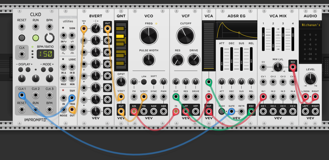
Another new patch to explore probability specifically. A CLKD clock triggers the Kinks S&H, which samples voltage from the 8VERT through a quantizer to set the VCO’s pitch. The clock also triggers the ADSR EG to gate the VCA. Standard clocked generative voice — every clock pulse produces a note.
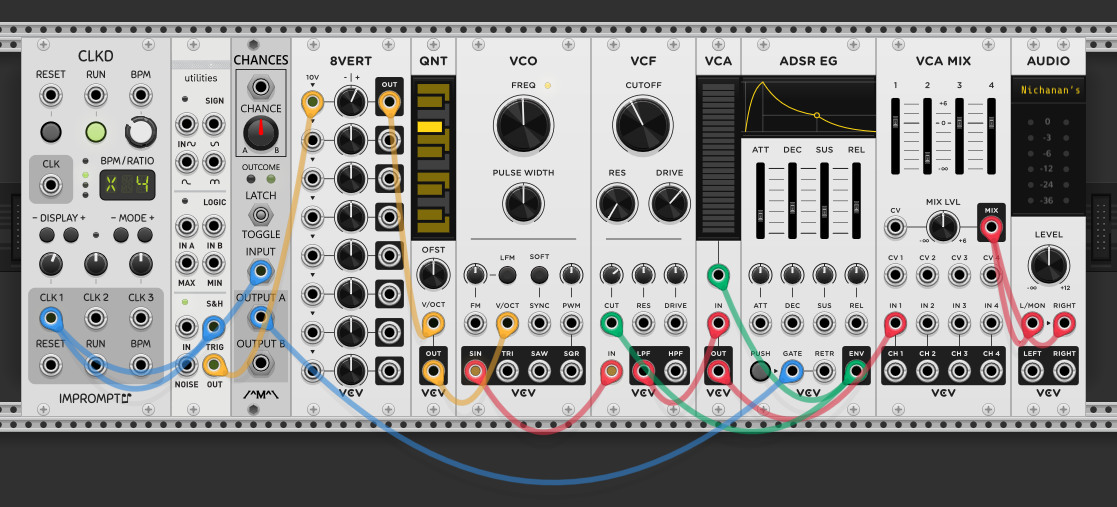
The Chances module (by Imprompter) — a more flexible take on the Bernoulli gate — is inserted between the clock and the voice’s gate. The clock goes into the Chances INPUT, and OUTPUT A now gates the ADSR instead of the clock directly. The CHANCE knob sets the probability that each incoming clock pulse passes through to output A — at 50%, roughly half the clock pulses reach the envelope, so the voice plays on about half the beats. The S&H still triggers on every clock pulse (pitch changes every beat), but the voice only sounds probabilistically. This means pitches are “skipped” silently — the melody has gaps, creating a sparser, less predictable rhythm from a steady clock.
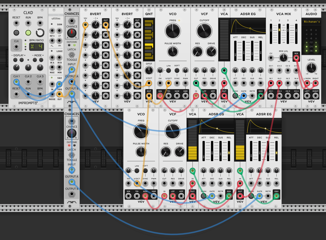
A second voice (VCO → VCF → VCA → ADSR EG → VCA → ADSR EG) is added with chained probability. The first Chances module’s OUTPUT B — the pulses that didn’t make it to voice 1 — feeds two places: it directly gates the second voice’s first ADSR, and it also feeds a second Chances module’s INPUT. The second Chances module’s OUTPUT A gates the second voice’s second ADSR. The second voice passes through two VCAs in series, each with its own envelope, so both envelopes must be open for the sound to pass.
The probability chain creates a hierarchy: voice 1 plays ~50% of beats (output A of the first Chances). Of the remaining ~50% that went to output B, some gate the second voice’s first envelope directly, and a further probabilistic subset gates its second envelope. The second voice only fully sounds when both its envelopes open — it’s rarer and sparser than voice 1. The two voices are complementary: they never play on the same beat (A and B are mutually exclusive), and the second voice has an additional layer of probability thinning it further.
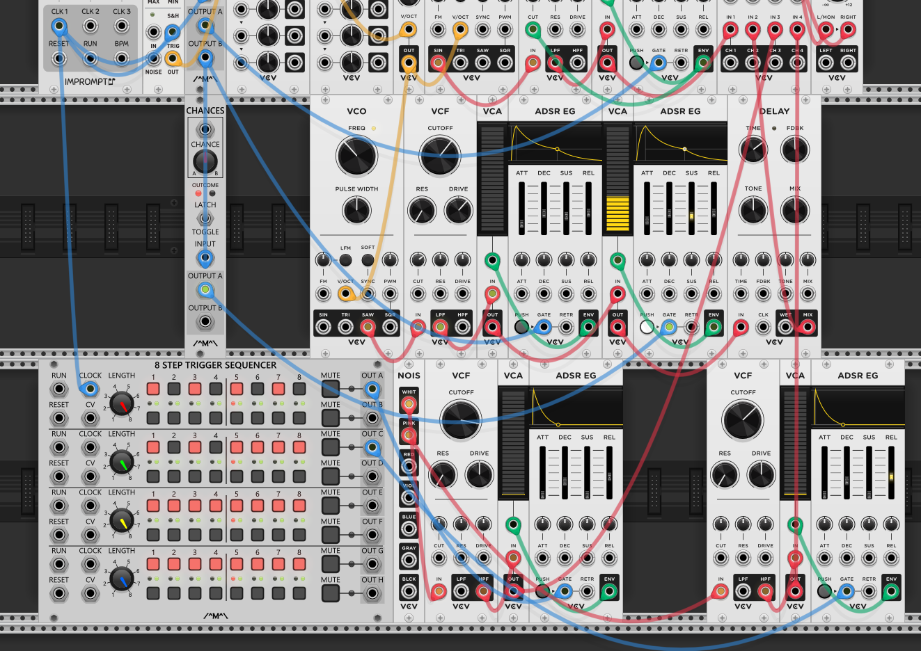
A percussion layer is added using an 8 Step Trigger Sequencer with multiple rows, each programming a different rhythmic pattern. A NOIS module provides different noise colors: white noise for the hi-hat and pink noise for the snare. Each noise source goes through its own VCF → VCA → ADSR EG chain, and different rows of the trigger sequencer gate each percussion voice independently. This gives direct per-step control over the rhythm — each row’s buttons toggle individual beats on or off, unlike the probability-driven melodic voices above.
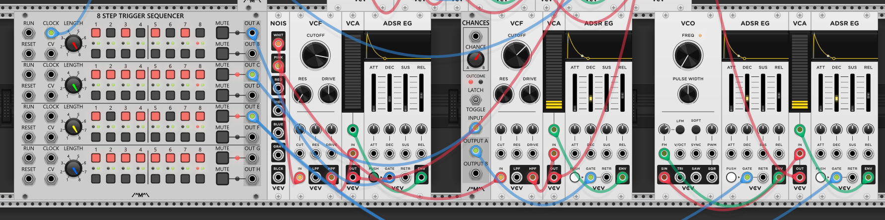
A Chances module is inserted into the snare’s gate path, so the snare now plays probabilistically — not every programmed beat fires, adding variation to the pattern without reprogramming the sequence. A bass drum voice is also added: a VCO (tuned low) through a VCF into a VCA gated by its own ADSR EG, triggered by another row of the trigger sequencer. The kick uses a pitched oscillator rather than noise (session 5 — synthesized percussion), giving it a tonal thump distinct from the noise-based hi-hat and snare.
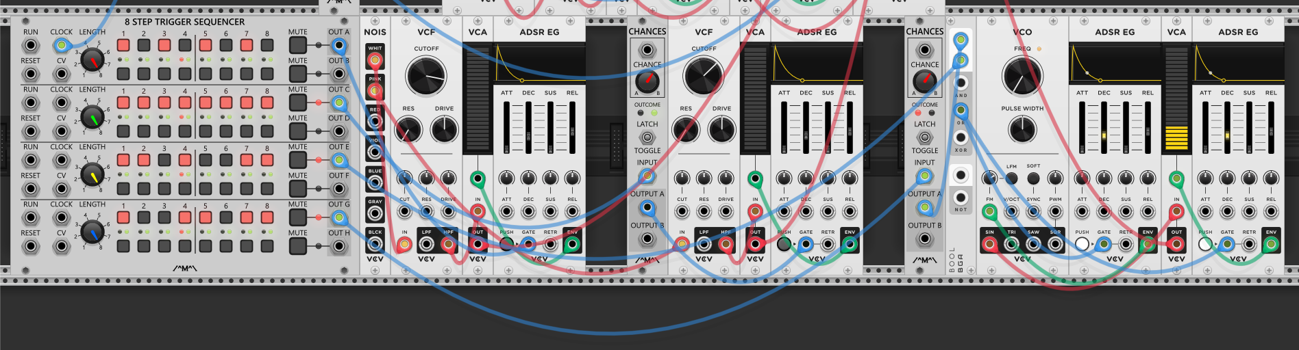
The bass drum gets probability via a combination of Chances and Boolean logic (session 10 — gate logic). Two rows of the trigger sequencer feed the kick: row 3 goes directly to a Boolean module, row 2 goes through a Chances module at 50% probability first, then its output also feeds the Boolean module. The Boolean outputs OR — so the kick fires whenever either row 3’s beat lands (guaranteed) or row 2’s beat passes the probability check. Row 3 provides the reliable backbone (the beats that always hit), while row 2 adds ghost kicks that come and go probabilistically. The kick pattern has a stable skeleton with variable fill — it never loses its groove but never plays exactly the same twice.