Basic Subtractive Voice
Starting point: the simplest patch
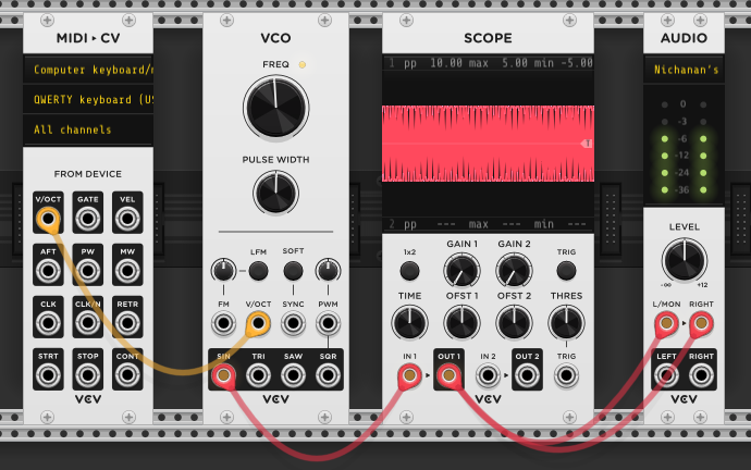
The most basic setup: an oscillator (VCO) plugged directly into an audio output. The VCO generates a sine wave — a smooth, repeating vibration at a fixed frequency. Analog oscillators produce slightly impure sines with trace harmonics, while digital oscillators can output mathematically perfect sine waves. That electrical signal goes to the speakers, which push air back and forth at the same rate. You hear a tone.
That’s it. One module making a signal, one module turning it into sound. Everything else in synthesis is about shaping, controlling, and modulating that signal before it reaches the output.
The MIDI-CV module is also connected here (yellow cable: V/OCT → VCO) so the keyboard can change the pitch. Higher key = higher voltage = faster vibration = higher note.
V/OCT means 1 volt = 1 octave, with each semitone approximately 0.083V (1/12th of a volt). The pitch relationship is linear — go up 1V, go up one octave — but because each octave doubles the frequency, the voltage-to-frequency curve is exponential: 0V = 440Hz, 1V = 880Hz, 2V = 1760Hz, 3V = 3520Hz. The oscillator has an exponential converter inside that makes this translation. Oscillator quality affects pitch tracking — better VCOs stay in tune across a wider octave range, while cheaper ones may drift sharp or flat at the extremes.
Building up: the full voice
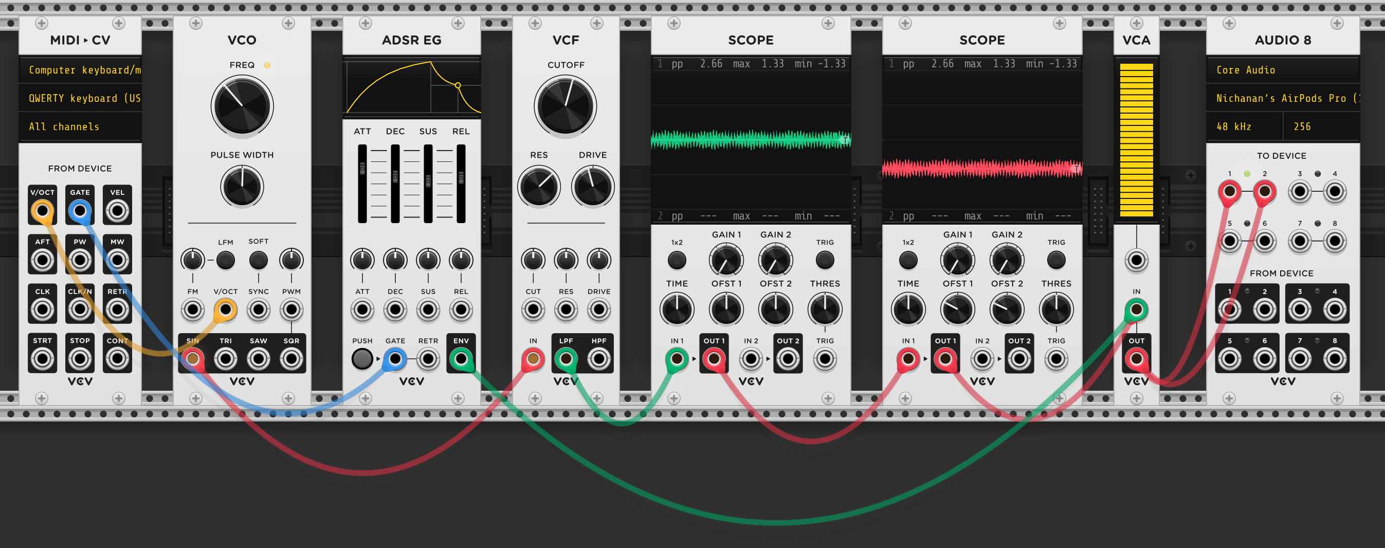
Adding a filter (VCF), envelope (ADSR), and amplifier (VCA) between the oscillator and the output turns the static tone into something that responds and changes over time.
You press a key on the keyboard. Two things happen simultaneously:
- The MIDI-CV module sends a pitch voltage (V/OCT) to the VCO, telling it what frequency to vibrate at.
- It also sends a gate signal to the ADSR. A gate stays high for as long as the key is held — +5V while pressed, 0V when released. It has duration. The ADSR starts its attack phase when the gate goes high, holds the sustain level for as long as the gate stays high, and begins the release phase when the gate drops. The length of your key press directly shapes the envelope.
A trigger is different — a brief pulse, a momentary spike that says “now” and immediately drops back to zero. It has no duration. A trigger would tell the ADSR to start but gives it no information about when to stop. Some modules use gates, some use triggers, and some accept both. The ADSR uses a gate because it needs to know both when a note begins and when it ends. Both are carried on blue cables because they’re all timing signals — they tell other modules when to do things, not what to do.
The VCO generates a raw tone and sends it through the audio chain: VCO → VCF → VCA → speakers. Meanwhile, the gate drives the ADSR envelope, which sends a control signal that changes shape over time — rising (attack), falling (decay), holding (sustain), then fading (release). This envelope modulates two things:
- ADSR → VCF cutoff — the filter sweeps open and closed over the life of each note. This is what gives the sound its animated, evolving quality — the timbre changes rather than staying static.
- ADSR → VCA — the amplifier opens and closes, giving the note its volume shape. Without this, sound would either be constantly on or constantly off. The envelope is what makes it fade in, sustain, and fade out.
The VCF here is a low-pass filter (LPF) — it passes frequencies below the cutoff and attenuates (progressively reduces) those above — frequencies past the cutoff are still present, just increasingly quiet. Other filter types exist: a high-pass filter (HPF) does the opposite (cuts lows, passes highs), and a band-pass filter (BPF) isolates a narrow band around the cutoff, cutting both above and below. Many filter modules offer all three as separate outputs.
Filters also have a slope measured in poles: each pole adds 6dB/octave of rolloff, so a 1-pole filter is 6dB/oct, a 2-pole is 12dB/oct (gentler), and a 4-pole is 24dB/oct (sharper, more aggressive). And a resonance control boosts frequencies right at the cutoff point, adding a whistling or singing quality. At extreme resonance, the filter self-oscillates — it becomes a sine wave oscillator at the cutoff frequency, producing a tone even with no input. Some filters have a V/OCT input so you can sequence the self-oscillation like a VCO.
A common technique is routing the same pitch CV to both VCO V/OCT and filter cutoff, so the filter opens wider for higher notes (keyboard tracking). Inverting the pitch CV gives the opposite — higher notes get darker.
The key insight: none of the audio signal is being changed directly. The envelope is a separate control signal that rides alongside the audio, opening and closing the filter and amplifier from the outside.
Final setup
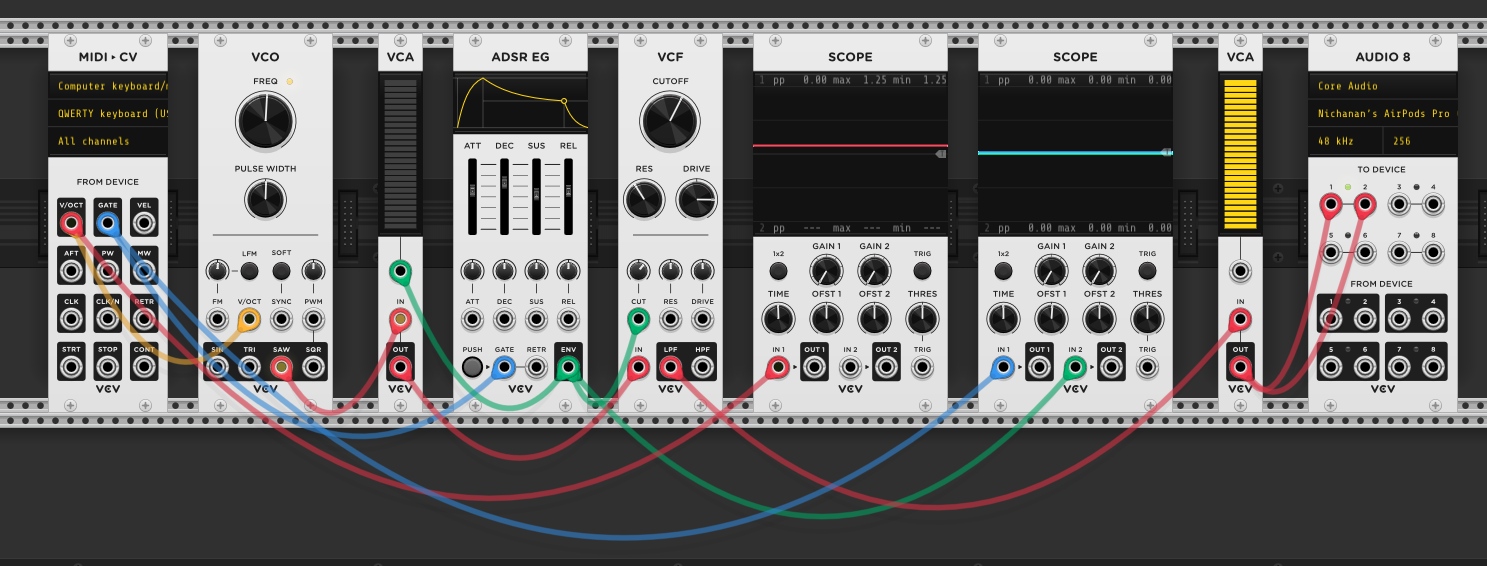
The final patch adds a second VCA before the filter and routes the envelope to all three destinations: 1st VCA (volume before filtering), filter cutoff (tonal shape), and 2nd VCA (final volume). The same ADSR shape controls all three — the note’s volume and brightness rise and fall together.
The signal path is now: VCO → VCA → VCF → VCA → Audio 8.
The gate signal is also sent to a scope, which lets you see the on/off timing of key presses — useful for understanding how gate duration relates to the envelope’s behaviour.
Adding an LFO
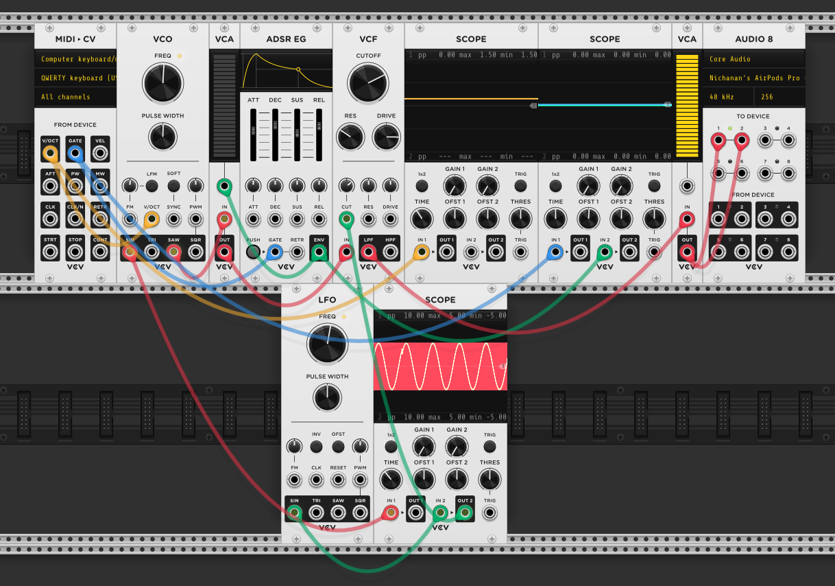
An LFO (low-frequency oscillator) is the same thing as the VCO but running far too slowly to be heard. Where the VCO vibrates hundreds or thousands of times per second to produce an audible tone, the LFO might cycle once or twice per second. You don’t listen to it. You use it to move things.
Here the LFO’s sine output is routed to the VCF cutoff alongside the envelope. The filter brightness now sweeps up and down in a continuous cycle, adding a wobble to the sound.
LFOs can be bipolar (oscillating between −5V and +5V) or unipolar (staying between 0V and +10V). This matters for modulation: a bipolar LFO sweeps a parameter above and below its set point, while a unipolar LFO only pushes it in one direction from the set point. An attenuverter can convert between them by scaling and offsetting the signal.
The ADSR and LFO behave differently as modulation sources. The ADSR is event-driven — it fires once when a gate arrives and follows its shape. The LFO is free-running — it cycles continuously regardless of whether you’re playing. During the release phase, as the envelope fades the note out, the LFO is still wobbling the filter cutoff. That flutter in the tail of a note is the LFO continuing to work while the ADSR lets go.
Concepts learned
Sound is vibration. An oscillator generates a repeating signal. Pitch = speed of vibration. Volume = size of vibration.
Waveforms matter. Sine is pure — no overtones. Sawtooth is rich with harmonics, giving the filter something to sculpt. If the source has no overtones, the filter has nothing to remove. Specifically, sawtooth contains all harmonics (1st, 2nd, 3rd…), which is why it sounds full. Square contains only odd harmonics (1st, 3rd, 5th…), giving it a hollow character. Triangle also contains only odd harmonics but at much lower amplitudes, making it close to a sine — that’s why it sounds soft. Square waves have a pulse width (duty cycle) — the proportion of time the waveform spends high vs low. When both durations are equal, it’s a true square wave. Modulating the pulse width with an LFO (PWM) changes the harmonic content over time, adding movement to the sound.
An envelope is a shape, not a sound. It describes how something changes over time (attack, decay, sustain, release). It needs to be routed to something — a filter, an amplifier — to have any effect. Many envelope generators have a retrigger input — sending a trigger while a gate is still held restarts the attack stage without waiting for the current envelope to finish, useful for overlapping notes. Some envelopes also offer selectable curve shapes (linear, exponential, logarithmic) per stage — a linear attack rises at a constant rate, an exponential attack accelerates into the peak, and a logarithmic release fades slowly then drops off quickly.
A gate has duration, a trigger does not. A gate stays high as long as the key is held — the ADSR uses this to know when to sustain and when to release. A trigger is a momentary pulse that only says “now.” Both are timing signals (blue cables), but they carry different information.
Modulation is routing a control signal to a parameter. One signal can modulate many things — the same ADSR feeds three destinations. Multiple sources can also stack on one parameter — the ADSR and LFO both feed VCF cutoff, their effects combining. In VCV Rack, you can stack multiple cables from the same output for free. In hardware, splitting one signal to multiple destinations requires a mult (multiplier) module — a dedicated splitter that copies the signal.
VCAs come in three flavours. A Voltage-Controlled Attenuator can only reduce a signal (0× to 1×). A Voltage-Controlled Attenuverter can reduce and invert (−1× to +1×). A Voltage-Controlled Amplifier can also boost above unity — useful for quiet signals that need a gain stage. Most VCAs in Eurorack are attenuators despite the name. Many VCAs also saturate when driven hard, coloring the sound with subtle harmonics — different VCA circuits saturate differently, giving each module a character. VCAs also have a response curve: linear (proportional — good for precise CV control) or exponential (opens up more dramatically at higher voltages — sounds more natural for volume envelopes because human hearing is logarithmic).
LFO → VCA = tremolo. In this patch the LFO modulates the filter. But patching an LFO into a VCA’s CV input instead creates tremolo — the volume pulses up and down rhythmically. Same modulation concept, different destination, completely different effect.
Event-driven vs free-running modulation. The ADSR responds to gates — it fires and stops. The LFO cycles continuously regardless of input. During a note’s release, the ADSR is fading out but the LFO keeps going.
Nothing happens without routing. Modules in the rack do nothing unless patched. The ADSR was present from the start but had no effect until connected.
Reference
Modules
- MIDI → CV — converts keyboard input into control voltages (V/OCT for pitch, GATE for note on/off)
- VCO — oscillator. Generates the raw tone
- ADSR EG — envelope generator. Produces a one-shot control signal shape triggered by a gate
- VCF — voltage-controlled filter. LPF (low-pass), HPF (high-pass), and BPF (band-pass) are common types. Slope measured in poles (2-pole = 12dB/oct, 4-pole = 24dB/oct). Resonance boosts at cutoff; at extremes, the filter self-oscillates
- VCA — voltage-controlled amplitude module. Despite the name, most are attenuators (reduce only). Can be linear (proportional response) or exponential (natural-sounding volume curves). Used for volume shaping with envelopes, tremolo with LFOs, or dynamic routing
- LFO — low-frequency oscillator. Produces a continuous, repeating control signal for modulation. Can be bipolar (−5V to +5V) or unipolar (0V to +10V)
- Audio 8 — output to speakers/headphones
Cable color coding (Omri Cohen convention)
- Red — audio signals
- Blue — clocks / gates / triggers
- Yellow — pitch information (V/OCT)
- Green — modulation (envelopes, LFOs)
Connections
| From | To | Cable | Role |
|---|---|---|---|
| MIDI V/OCT | VCO V/OCT | yellow | Key press sets oscillator frequency |
| MIDI GATE | ADSR GATE | blue | Key held/released triggers envelope start/release |
| MIDI GATE | Upper Scope | blue | Visualises gate timing on scope |
| ADSR ENV | 1st VCA CV | green | Envelope shapes volume before filtering |
| ADSR ENV | VCF CUT | green | Envelope sweeps filter brightness per note |
| ADSR ENV | 2nd VCA CV | green | Envelope shapes final volume — note fades to silence |
| LFO SIN | VCF CUT | green | Continuous wobble on filter brightness |
| LFO SIN | Lower Scope | green | Visualises LFO cycle on scope |
| VCO SIN | 1st VCA IN | red | Raw oscillator tone enters first amplifier |
| 1st VCA OUT | VCF IN | red | Shaped audio enters filter |
| VCF LPF | Scope / 2nd VCA | red | Filtered audio to scope and final amplifier |
| 2nd VCA OUT | Audio 8 | red | Final shaped audio to speakers |