Sequencers
Clock and sequencer basics
In Session 1, you played notes by pressing keys — the keyboard sent gates and pitch voltages. Here, a clock and sequencer replace you. The clock decides when, the sequencer decides what.
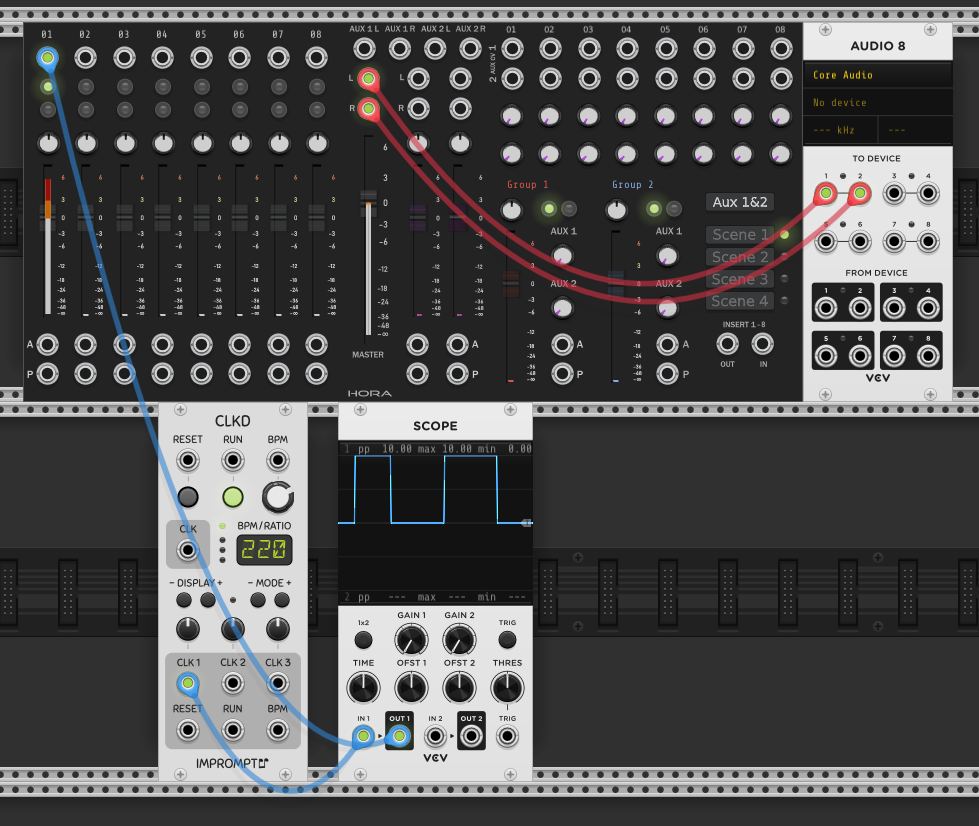
A clock (CLKD, Impromptu) sends a regular pulse at a set tempo — here 220 BPM. Each pulse is a brief spike of voltage, repeating at a steady rate. The scope shows this: a square wave, high-low-high-low.
A sequencer (Hora, the black module with 8 steps) receives that clock and advances one step on each pulse. Each step can have its own settings — pitch, gate on/off, velocity. The green lights indicate which steps have active gates. The pattern you hear is a heartbeat-like doubled beat — comes from which steps are enabled and which are silent.
The clock signal goes from CLKD to the sequencer (blue cable — it’s a timing signal). The sequencer’s audio output routes through the Hora mixer to Audio 8 (red cables).
| From | To | Cable | Role |
|---|---|---|---|
| CLKD CLK | Sequencer CLK | blue | Clock pulse advances sequencer one step |
| Sequencer OUT | Hora mixer | red | Audio to mixer |
| Hora mixer OUT | Audio 8 | red | Audio to speakers |
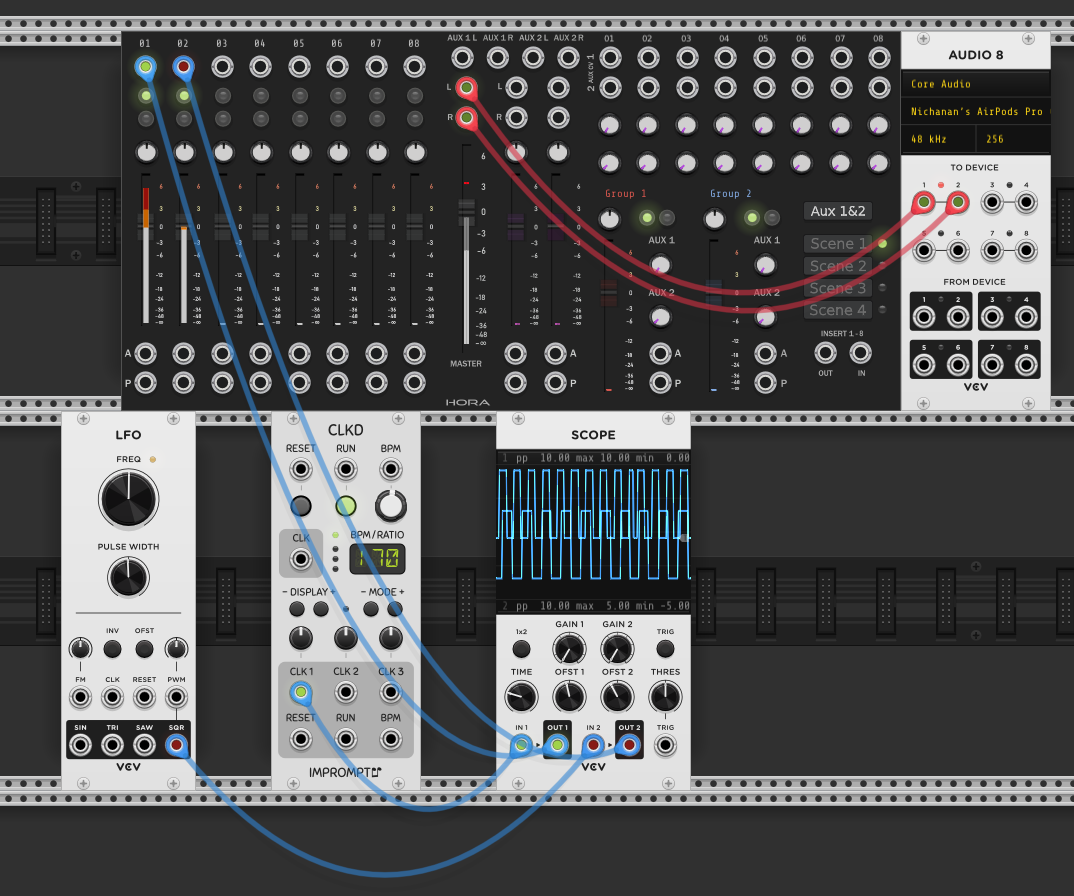
A dedicated clock module isn’t the only way to generate a clock signal. An LFO’s square wave output works too — it’s already a repeating high/low signal, which is exactly what a clock is. The scope here shows both: the CLKD clock and the LFO square wave side by side. They’re the same kind of signal at different rates.
In Session 1, the LFO was a modulation source for the filter. Here it’s doing something structurally different, driving timing rather than shaping sound. But the underlying signal is the same. A square wave is a square wave. What matters is where you route it.
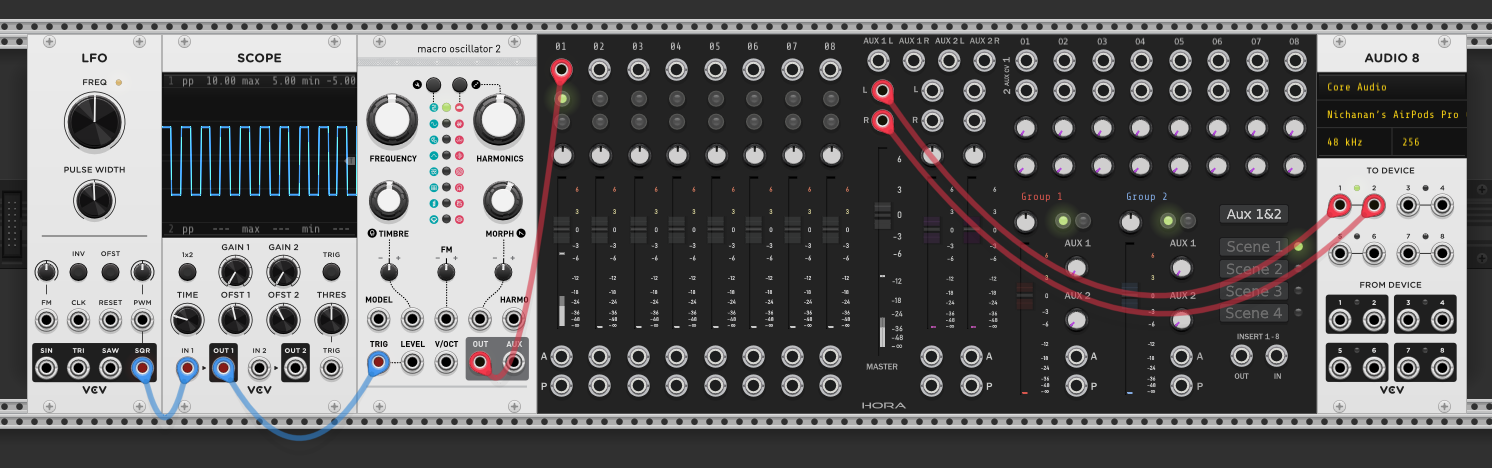
Taking it further: the LFO’s square wave patched directly into Macro Oscillator 2 (Plaits)‘s TRIG input. No clock module, no sequencer — just the LFO’s rising edge triggering Plaits to fire a new sound event on each cycle. Plaits has its own internal envelope, so it doesn’t need an external ADSR.
This is the most stripped-down version of automated timing: one signal saying “now” over and over. The LFO rate controls how often it fires. If you patched the VCO’s square output here instead, it would trigger thousands of times per second — you’d hear a buzzy tone rather than distinct rhythmic hits. The difference between a clock and an audio oscillator is just speed.
| From | To | Cable | Role |
|---|---|---|---|
| LFO SQR | Plaits TRIG | blue | LFO rising edge triggers Plaits directly |
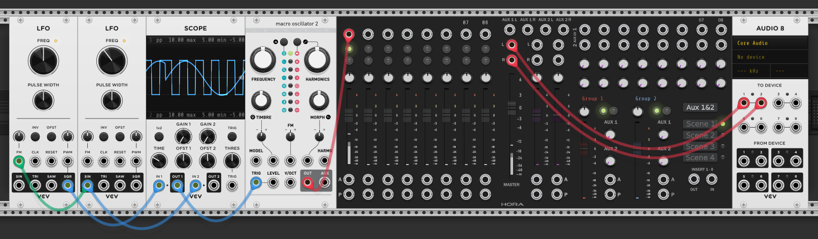
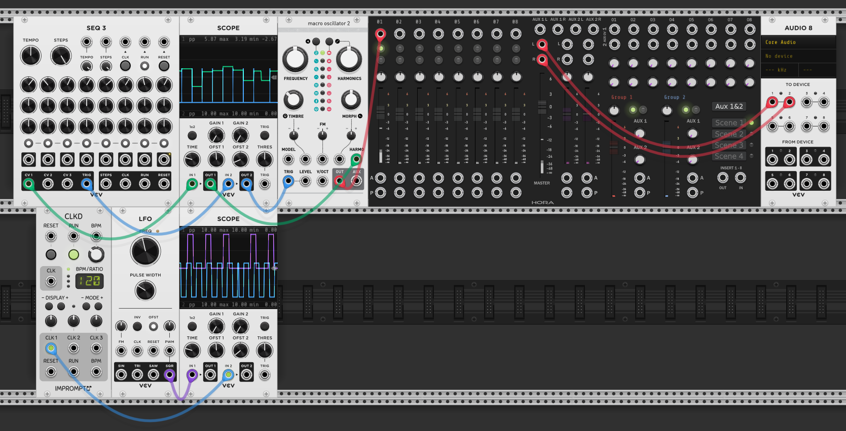
Adding a second LFO: the first LFO’s square wave still triggers Plaits (blue cable to TRIG), same as before. The second LFO’s sine output is patched into the first LFO’s FM input (green cable), modulating its frequency. This means LFO 1’s rate speeds up and slows down following LFO 2’s sine cycle — the trigger rhythm isn’t steady anymore, it breathes.
The scope shows the result: the square wave on top (LFO 1) has uneven spacing because its frequency is being pushed around by the sine wave below (LFO 2). One LFO controls when, the other controls how fast “when” changes.
This is modulation of a modulation source — LFO 2 doesn’t touch Plaits directly, it shapes the behaviour of LFO 1, which in turn drives Plaits.
| From | To | Cable | Role |
|---|---|---|---|
| LFO 2 SIN | LFO 1 FM | green | Modulates LFO 1’s rate — rhythm breathes |
Back to the sequencer, but now it’s doing more than just triggering. SEQ 3 has its own internal tempo — no external clock needed. Each step has rows of knobs (CV1, CV2, CV3) that set a voltage level. The CV1 output is patched to Plaits’ HARMONICS input (green cable — it’s modulating timbre), and TRIG goes to Plaits’ TRIG (blue cable).
On each step, the sequencer does two things simultaneously: fires a trigger (“now”) and sends a voltage from the CV1 knob position (how much harmonics). The upper scope shows the CV1 output as a staircase — each plateau is one step’s knob value, stepping through in sequence. The result is a repeating pattern where Plaits’ harmonic content changes on every beat.
This is the sequencer acting as a parameter controller, not just a trigger source. The knobs are voltages, and those voltages can be routed to any CV input on any module — harmonics here, but it could just as easily be filter cutoff, pitch (V/OCT), or anything else with a CV input.
| From | To | Cable | Role |
|---|---|---|---|
| SEQ 3 CV1 | Plaits HARMONICS | green | Sequencer controls timbre per step |
| SEQ 3 TRIG | Plaits TRIG | blue | Sequencer triggers each step |
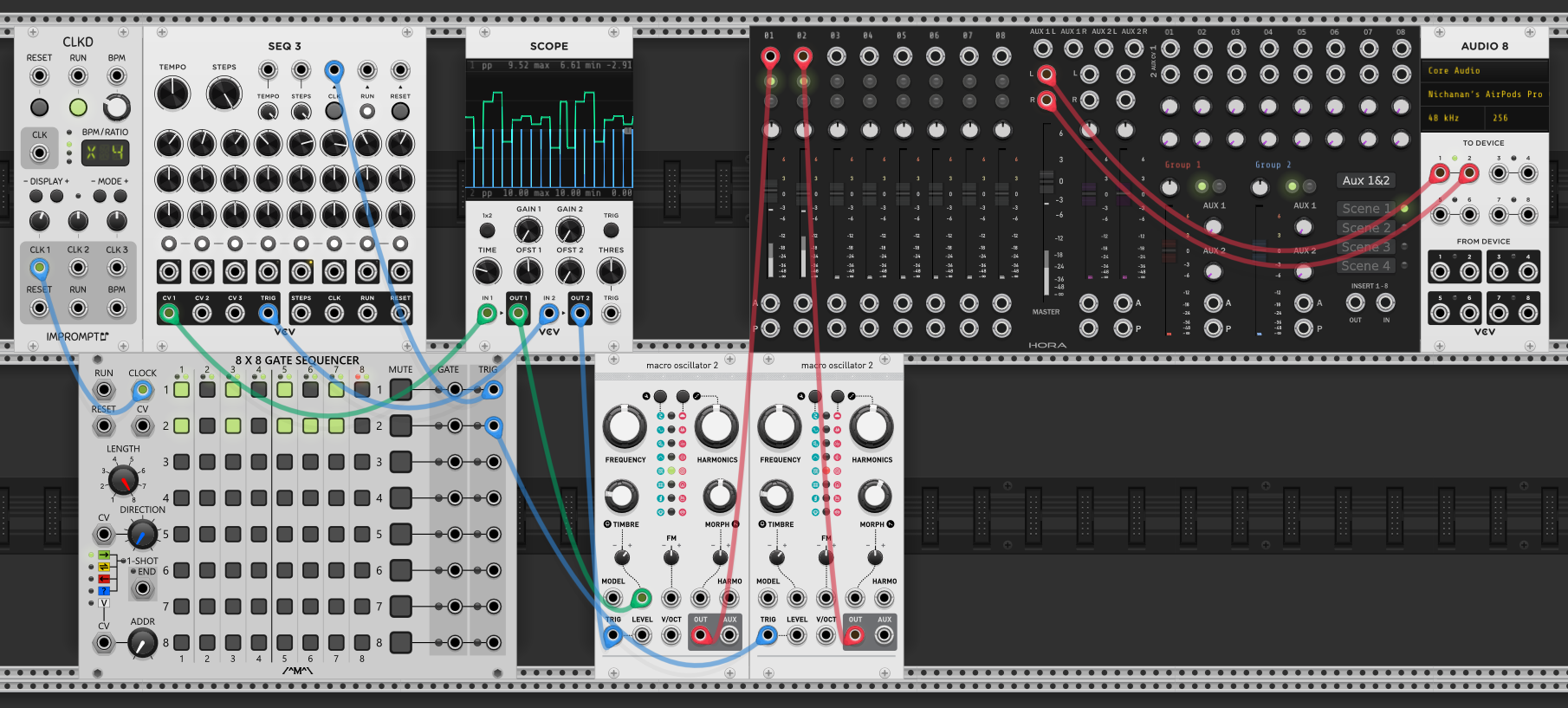
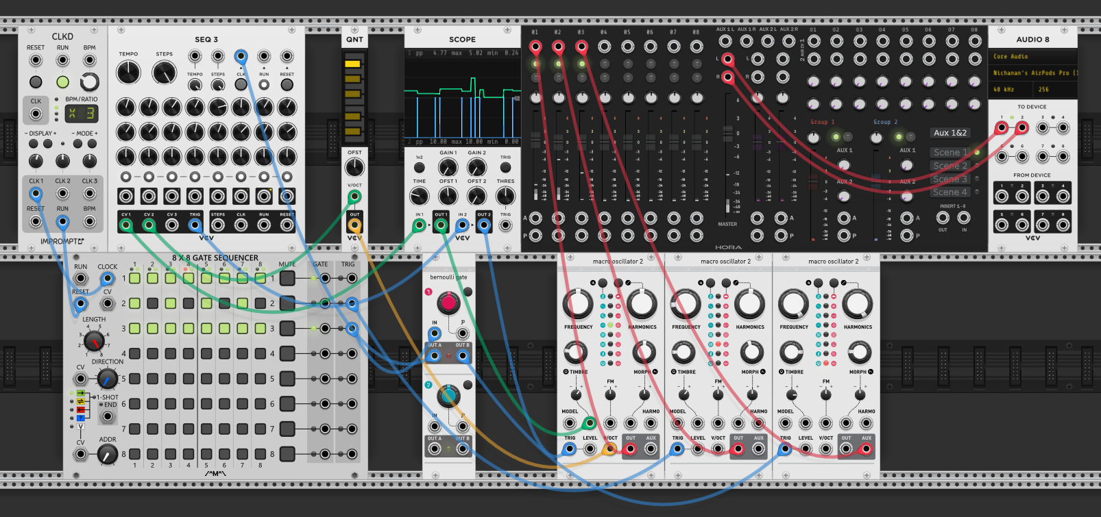
Adding a gate sequencer and a second Plaits. Trigger sequencers output short pulses (for percussion and function generators), while gate sequencers output sustained high signals — a gate held across multiple steps produces tied/legato notes. The clock chain flows: CLKD → 8x8 Gate Sequencer → SEQ 3. The gate sequencer sits between the master clock and SEQ 3, so its grid pattern determines which clock pulses actually reach SEQ 3. Beats where row 1 is active pass through; silent beats are swallowed.
SEQ 3 still sends CV1 to the first Plaits’ HARMONICS (green cable) and TRIG to its TRIG input (blue cable) — same as before. The second Plaits is triggered directly by row 2 of the gate sequencer (blue cable), independently of SEQ 3.
The two Plaits modules are set to different models — one pitched, one noise/percussion. Both route to the Hora mixer (red cables), then to Audio 8. The gate sequencer’s grid is like a drum machine: each row is a voice, each column is a beat, lit buttons mean “fire.” Row 1 controls the pitched voice’s rhythm (via SEQ 3), row 2 controls the percussion independently. One master clock drives both patterns.
| From | To | Cable | Role |
|---|---|---|---|
| CLKD CLK | Gate Seq CLOCK | blue | Master clock drives the grid |
| Gate Seq Row 1 | SEQ 3 CLK | blue | Row 1 pattern filters clock to sequencer |
| Gate Seq Row 2 | Plaits 2 TRIG | blue | Row 2 triggers percussion directly |
| Plaits 1 OUT | Hora mixer | red | Pitched voice to mixer |
| Plaits 2 OUT | Hora mixer | red | Percussion voice to mixer |
Tempo and rhythmic density are independent controls. The clock (CLKD) sets the actual BPM — how fast time moves. The gate sequencer’s grid sets how many of those beats produce sound. You can slow the clock way down but activate more steps on the grid, and the result sounds faster because more events are firing per cycle, even though each beat is further apart.
This is the same separation of concerns from the gate sequencer patch above: the clock decides when beats exist, the gate sequencer decides which beats are heard. Turning up density on the grid while turning down BPM on the clock gives you a slow-moving pattern that feels busy — more notes per loop, fewer loops per minute.
Run and reset
Run is play/pause — it starts or stops the clock from sending pulses. Everything downstream freezes in place when you stop.
Reset sends all connected modules back to step 1. Sequencers jump to the beginning, LFOs restart their cycle. It doesn’t stop the clock — it just says “start over.” You can reset while running and the pattern snaps back to the top and keeps going.
CLKD has Run and Reset outputs (bottom of the module) that you patch to the matching inputs on your sequencers. If you don’t connect the reset output to your sequencer’s reset input, hitting reset on CLKD won’t reset the sequencer — they’ll be out of sync. Same with run. Each module needs to be told independently.
Patch the clock’s Run output to the sequencer’s Reset input so the sequencer resets to step 1 automatically when the clock is restarted.
Pitch sequencing
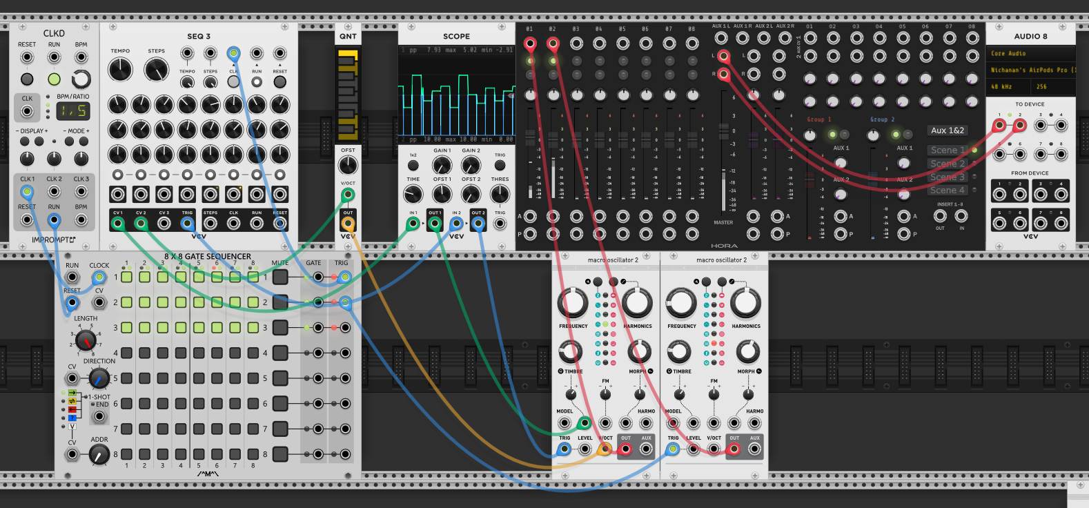
Adding a quantizer (QNT) between the sequencer and the oscillator. SEQ 3’s CV2 output sends a raw voltage to QNT’s V/OCT input (green cable). The quantizer snaps that voltage to the nearest note in the selected scale, then its output goes to the first Plaits’ V/OCT (yellow cable).
Without the quantizer, the sequencer knobs produce arbitrary voltages — most land between notes, so the pitch sounds out of tune. The quantizer forces every value onto a real note. You set the knobs loosely and the quantizer cleans them up. CV1 still controls HARMONICS on the same Plaits (green cable from step 5 above), so now each step has both a pitch and a timbre change.
| From | To | Cable | Role |
|---|---|---|---|
| SEQ 3 CV2 | QNT V/OCT | green | Raw voltage to quantizer |
| QNT OUT | Plaits V/OCT | yellow | Quantized pitch to oscillator |
Probability with Bernoulli gates
A Bernoulli gate takes one trigger input and randomly sends it to one of two outputs — A or B — based on a probability knob. Here, row 3 of the gate sequencer feeds the Bernoulli gate’s input (blue cable). Out A clocks SEQ 3 (blue cable), out B triggers a third Plaits set to a hi-hat sound (blue cable). All three Plaits route to the mixer (red cables).
Each time row 3 fires, the Bernoulli gate flips a coin: either the sequencer advances (pitched melodic voice) or the hi-hat triggers, but not both. The probability knob controls the bias — turn it toward A and the melody dominates, toward B and the hi-hats take over.
This introduces controlled randomness without chaos. The when is still locked to the grid, but which voice plays on each beat is probabilistic. The overall rhythm stays steady while the texture shifts unpredictably between melody and percussion.
| From | To | Cable | Role |
|---|---|---|---|
| Gate Seq Row 3 TRIG | Bernoulli IN | blue | Grid trigger enters coin flip |
| Bernoulli OUT A | SEQ 3 CLK | blue | Heads: sequencer advances |
| Bernoulli OUT B | Plaits 3 TRIG | blue | Tails: hi-hat fires |
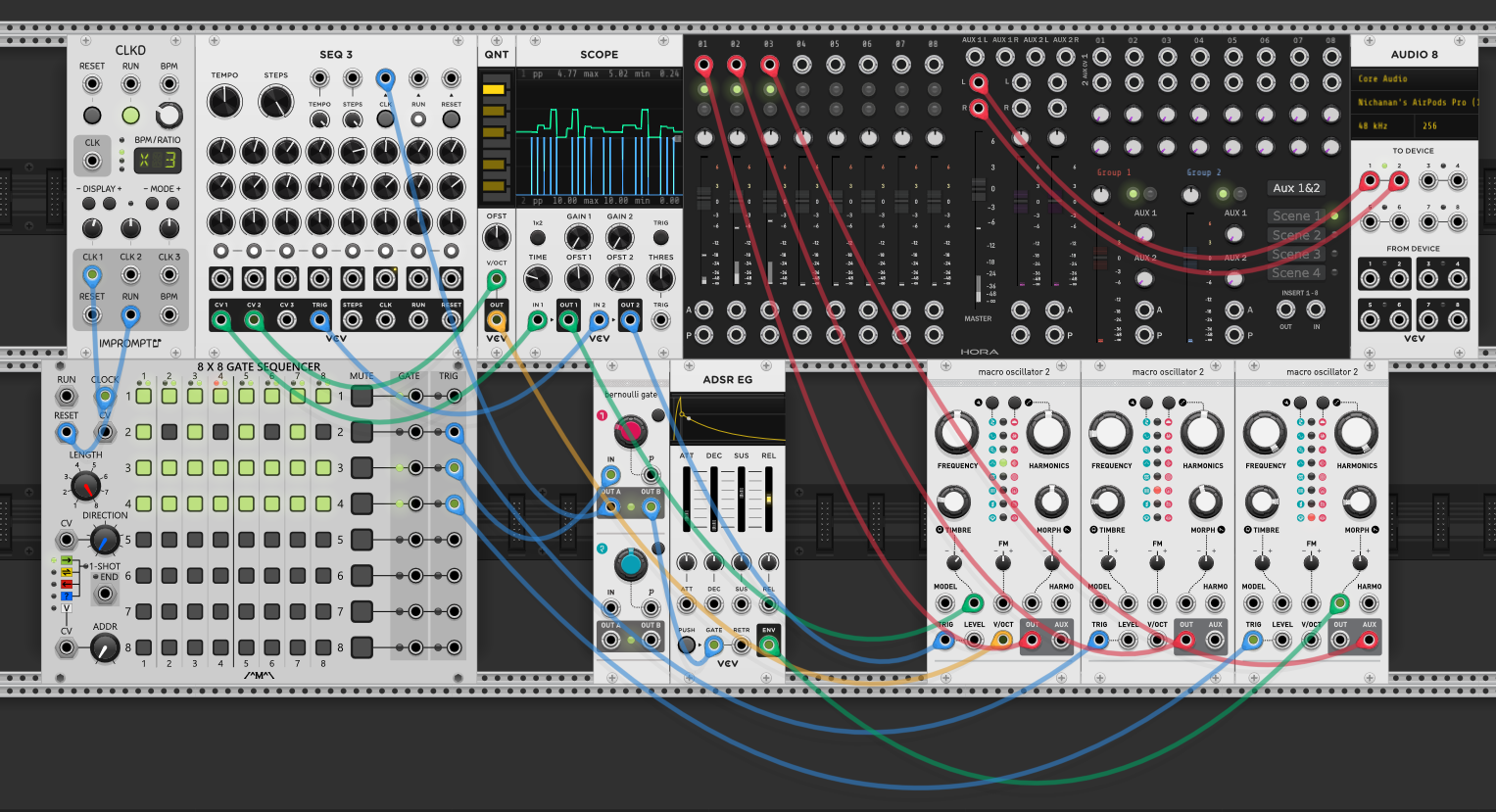
The Bernoulli gate doesn’t have to route to a voice — it can route to modulation. Here, Out B feeds an ADSR’s gate input (green cable). The ADSR’s envelope output goes to the first Plaits’ MORPH input (green cable). When the coin flip lands on B, the ADSR fires and sweeps the oscillator’s morph parameter through an envelope shape. When it lands on A, morph stays untouched.
The result is random timbral variation on the melodic voice — some notes get a morph sweep, others don’t. Green cables for both connections because this is a modulation path: the Bernoulli gate decides whether to modulate, the ADSR shapes how.
| From | To | Cable | Role |
|---|---|---|---|
| Bernoulli OUT B | ADSR GATE | green | Random trigger fires envelope |
| ADSR ENV | Plaits MORPH | green | Envelope sweeps morph parameter |
Clocking effects
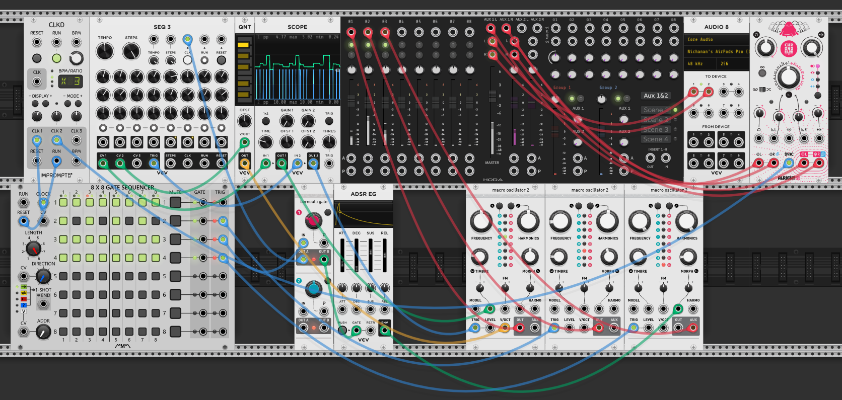
Adding a delay effect (Chronoblob) as a send effect via the mixer’s aux bus. The Hora mixer’s AUX 1 and AUX 2 outputs send audio to Chronoblob’s inputs (red cables — it’s audio). Chronoblob’s outputs return to the mixer’s L and R inputs (red cables). Each channel’s aux send knob controls how much of that voice goes to the delay.
The key connection: CLK 2 from CLKD goes to Chronoblob’s SYNC input (blue cable). This locks the delay time to the clock tempo — the echoes land on the beat instead of drifting. Without sync, you’d have to dial in the delay time by hand and it would fall out of time if you changed the BPM. With it, the delay stays rhythmically locked no matter what tempo you set.
| From | To | Cable | Role |
|---|---|---|---|
| Hora AUX 1/2 | Chronoblob IN | red | Audio send to delay |
| Chronoblob OUT | Hora L/R | red | Delayed audio returns to mixer |
| CLKD CLK 2 | Chronoblob SYNC | blue | Locks delay time to tempo |
Separating pitch and gate events
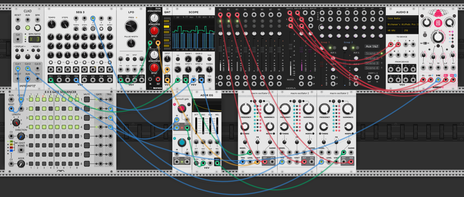
Replacing the sequencer’s CV2 → quantizer pitch path with an LFO and attenuverter. The LFO’s sine output goes to the attenuverter input (green cable — it’s modulation at this stage), and the attenuverter output goes to the first Plaits’ V/OCT (yellow cable — now it’s pitch).
Pitch is now a smooth, continuous sweep instead of discrete steps. The sine wave rises and falls on its own cycle, unsynced from the clock. The gate sequencer and Bernoulli gate still control when the voice sounds, but what pitch it lands on depends on where the LFO happens to be at that moment. The melodic contour drifts against the rhythm — each trigger catches the LFO at a different point in its cycle.
The attenuverter scales and offsets the LFO’s voltage. Without it, the full swing would cover a huge pitch range. Turning the attenuverter knob down narrows the sweep; the offset centers it around a particular note.
This is the separation: gates and pitch are now driven by completely independent sources. The rhythm is deterministic (grid + probability), the melody is free-running (LFO). Neither knows about the other.
| From | To | Cable | Role |
|---|---|---|---|
| LFO SIN | Attenuverter IN | green | Continuous pitch sweep (modulation stage) |
| Attenuverter OUT | Plaits V/OCT | yellow | Scaled pitch to oscillator |
Self-playing basslines
Adding an entirely independent bass voice on the bottom row: its own LFO → attenuverter → quantizer → Plaits chain. The LFO sweeps a sine wave through the attenuverter (green cable), the attenuverter output goes to the quantizer (yellow cable), and the quantizer snaps the continuous sweep to scale notes before sending it to the fourth Plaits’ V/OCT (yellow cable). The bass Plaits routes to the mixer (red cable).
This voice has no connection to the gate sequencer or the Bernoulli gate — it plays itself. The LFO determines the pitch contour, the quantizer keeps it in key, and Plaits’ internal envelope handles the articulation. It runs on its own timing, drifting against the clock-locked rhythm of the other three voices.
The quantizer makes the difference between this and the pitch/gate separation patch: without it, the LFO produces a smooth portamento. With it, the pitch jumps in discrete scale steps — it sounds like a bassline rather than a slide.
| From | To | Cable | Role |
|---|---|---|---|
| LFO SIN | Attenuverter IN | green | Continuous sweep |
| Attenuverter OUT | QNT IN | yellow | Scaled voltage to quantizer |
| QNT OUT | Plaits V/OCT | yellow | Quantized pitch — stepped bassline |
Concepts learned
- Clock as single timing source — one clock drives sequencers, gate patterns, and effects (Chronoblob sync). Everything rhythmic traces back to CLKD
- Gate sequencer as rhythmic filter — the grid decides which clock pulses pass through. Activating more steps at a lower BPM makes a pattern sound faster without changing tempo
- Sequencer direction modes — many sequencers offer direction modes beyond forward — pendulum (forward then backward), random step order — which produce different melodic patterns from the same step values
- Run and reset — run is play/pause, reset returns to step 1. Patch run output to sequencer reset input for automatic reset on each play
- Sequencer as parameter controller — CV rows are voltages that can modulate any parameter, not just pitch
- Quantizer — snaps arbitrary voltages to scale notes. Place it between a voltage source and V/OCT to stay in key
- Keyboard transpose — patching a keyboard’s V/OCT output to a sequencer’s transpose input transposes the entire running sequence in real time — a performance technique for key changes without reprogramming
- Bernoulli gate — probability-based routing. One trigger in, coin flip decides which of two outputs fires. Use it to split between voices or between triggering sound vs. triggering modulation
- Attenuverter — scales and offsets a signal. Essential for taming LFO range before it hits V/OCT or other sensitive inputs
- Separating pitch from gates — rhythm and melody can be driven by independent sources. Gates from the sequencer grid, pitch from a free-running LFO. Neither needs to know about the other
- Send effects via aux bus — mixer aux sends route audio to effects, returns come back to the mixer. Clock-synced delay keeps echoes on the beat
Reference
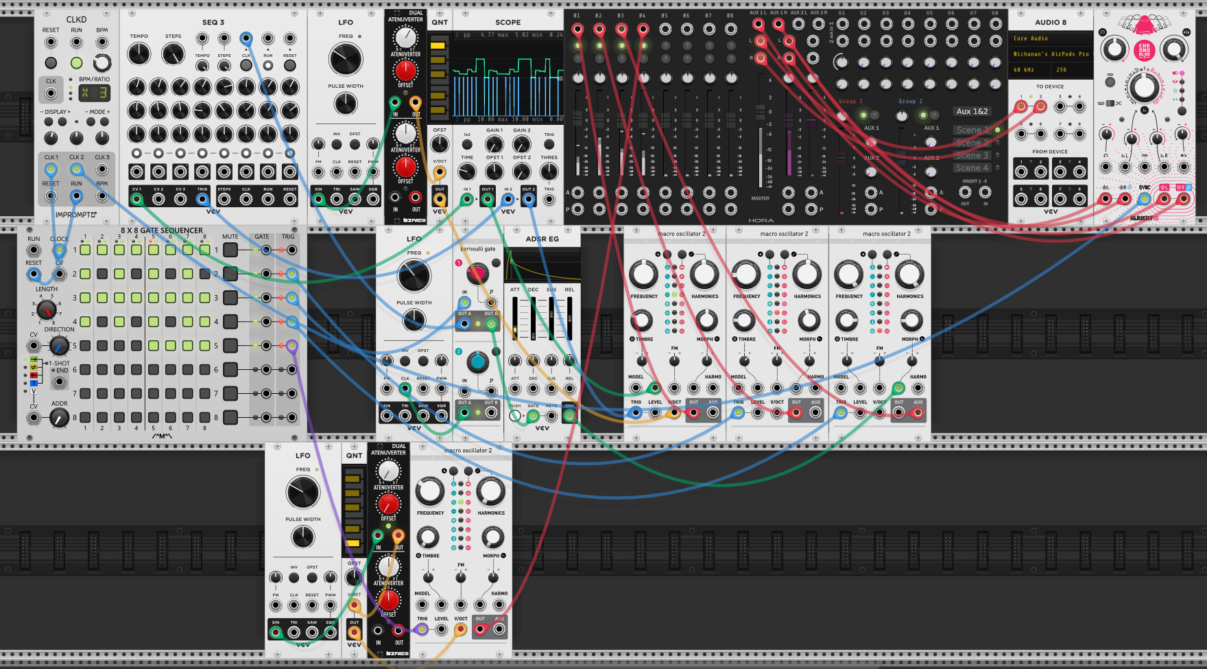
- Modules used: CLKD + Impromptu (clock), SEQ 3 (sequencer), 8x8 Gate Sequencer (rhythm grid), Bernoulli Gate (probability), LFO, Dual Attenuverter, QNT (quantizer), ADSR EG (envelope), Macro Oscillator 2 / Plaits (voices), Hora mixer, Chronoblob (delay), Scope, Audio 8
- Cable colors: red = audio, blue = clocks/gates/triggers, yellow = pitch, green = modulation