Gate Logic
Mults — copying signals to multiple destinations
In VCV Rack, stacking cables on an output acts as a built-in mult — no signal loss. In hardware, you need a dedicated mult module. There are two types:
- Passive mults — electrical junctions with no active circuitry. Each connected destination draws current, and the source voltage can sag under the combined load.
- Buffered mults — an op-amp re-drives the signal at full strength per output. No voltage loss regardless of how many destinations are connected.
For pitch CV, always use buffered — V/OCT is precise enough that even a few millivolts of sag shifts the pitch audibly. In hardware, stackable cables (with pass-through jacks at each plug) offer a third option for signal splitting alongside passive and buffered mults — no module needed.
Normalled connections: within a mult, inputs are internally routed to each other. If the first input receives a signal, the second input picks it up automatically without a separate cable.
Sample delay in VCV
Every module in VCV adds a 1-sample delay to the signal passing through it. Most of the time this is imperceptible, but it can cause sync issues when timing-critical signals (like clock or trigger) pass through different numbers of modules before reaching their destinations — one path arrives a sample or two later than the other.
Boolean logic — combining gates
Boolean logic operates on gate signals: high = true, low = false. Three core functions:
- AND: output is high only when both inputs are high. Drops low the moment either input closes.
- OR: output is high when either or both inputs are high. Only drops low when both are closed.
- XOR (exclusive or): output is high when exactly one input is high. Closes when both are high or both are low — it detects disagreement.
- NOT: inverts a gate signal — output is high when input is low, and vice versa. Useful for “play when the kick is silent” type patches where you want events to happen in the gaps of another pattern.
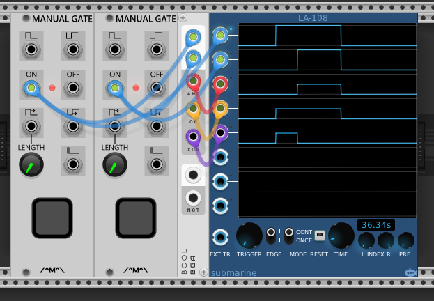
The analyzer confirms the behavior: with both manual gates held open, the top two traces (the individual gates) are high, AND is high, OR is high, but XOR drops to low — both inputs agree, so XOR shuts off.
Boolean gates as rhythmic triggers
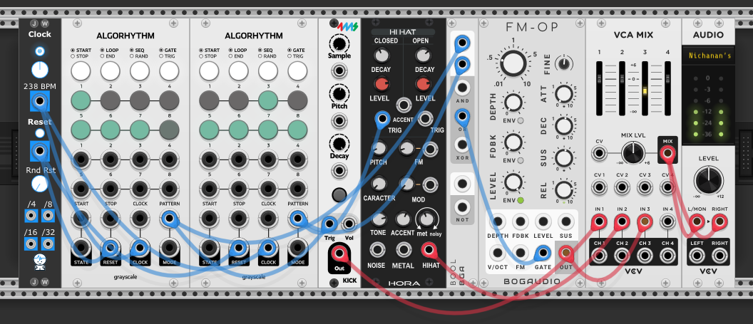
A clock (blue cables) drives two Algorhythm modules — one generating a kick pattern, the other a hi-hat pattern. The kick module triggers a Hora Kick drum, the hi-hat module triggers an MMS Hi Hat. Both gate outputs also feed a Bool logic module.
The Bool module’s AND, OR, or XOR output (blue cable) gates the FM-OP voice. By switching which logic output is patched to the FM-OP’s gate input, the same two rhythmic patterns produce different triggering behaviors:
- AND: FM-OP plays only on beats where kick and hi-hat fire together — the intersection of both patterns
- OR: FM-OP plays whenever either fires — the union, a busier rhythm
- XOR: FM-OP plays when exactly one fires — the beats where they disagree, creating a complementary rhythm that fills the gaps
The kick and hi-hat play their own sounds regardless. The boolean logic combines the two rhythm section sequencers to derive when the FM-OP voice plays — its rhythm isn’t independently programmed, it’s a logical product of the kick and hi-hat patterns.
The FM-OP’s level must follow its envelope (ENV knob up) with a short decay and release — otherwise the gate opens the voice but nothing closes it, producing a continuous tone instead of percussive hits.
Analog logic — combining continuous signals
Boolean logic works with gates: on or off. Analog logic extends the same idea to any signal — modulation, pitch CV, even audio rate. Instead of AND/OR/XOR, analog logic gives you max and min: at every moment, the output follows whichever input is highest (max) or lowest (min).
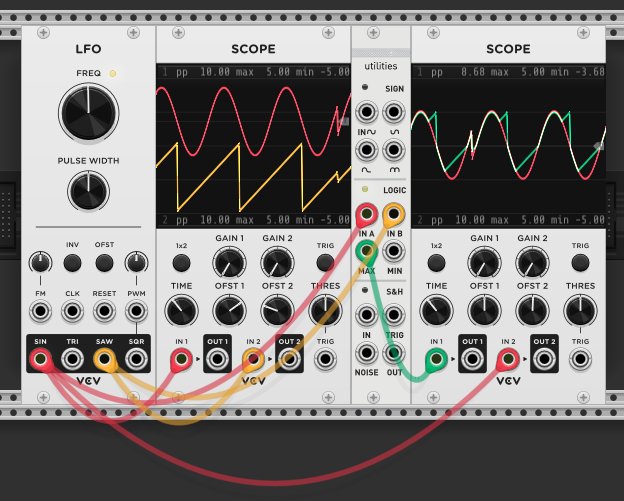
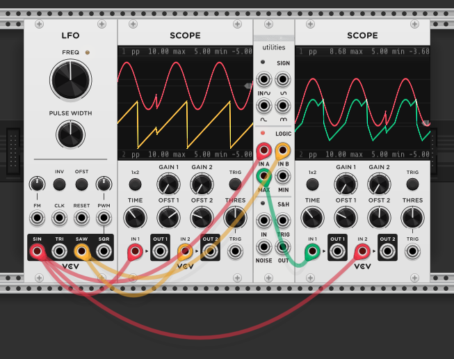
A sine and saw from the same LFO feed the Logic section of the Kinks utilities module (session 7 — S&H). Two inputs (In A, In B), two outputs (max, min). The max output traces the upper envelope of both signals — at any point it follows whichever waveform is higher. The min output traces the lower envelope — always following whichever is lower.
The result is new waveshapes that aren’t available from any single oscillator. The max output has the peaks of both waveforms stitched together, and the min has the troughs. These can be used as modulation sources, creating movement that’s more complex than either input alone.
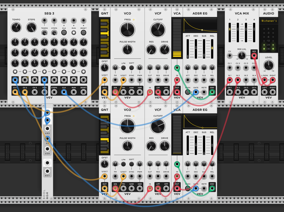
Deriving a third melody from two sequences
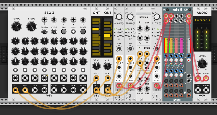
SEQ 3’s first two rows (yellow cables) each go through a quantizer into an LVCO — two independent melodic voices. The two quantizer outputs (pitch CV) also feed the Kinks Logic inputs (In A and In B). The max output drives a third LVCO’s V/OCT input, whose audio goes into the mixer alongside the other two voices (red cables).
Important: the Logic inputs must receive pitch CV, not audio. Feeding the LVCO audio outputs into Logic causes max/min to compare the raw waveforms sample-by-sample — this produces waveshaped noise, not a melody. The logic needs to compare the slow-moving pitch voltages so it can select whichever note is higher as a clean CV for the third oscillator.
While the logic gates are designed for binary signals, feeding audio through them intentionally produces crunchy distortion — oscillator output through XOR or AND creates bit-crushed textures with harsh overtones. It’s a crude effect but a legitimate creative tool when you want digital grit.
The third voice always plays whichever of the two input pitches is higher at any given step. It’s not a random melody and it’s not independently sequenced — it’s derived from the relationship between the other two. When voice 1 plays a higher note than voice 2, the third voice follows voice 1; when voice 2 is higher, it follows voice 2. The result is a third melodic line that’s harmonically related to both parents but identical to neither.
Combining gates with logic
Two full voice chains share the same SEQ 3 sequencer. The first voice receives the clock gate directly (blue cable) and plays on every step. The second voice’s gate is routed through a Bool logic module — the sequencer’s gate pattern is ANDed with a gate sequence that only opens on steps 1 and 4, so the second voice only sounds on those beats.
Both voices play the same pitch sequence but with different timbres (separate VCO → VCF → VCA → ADSR chains) and different rhythmic densities. The first voice carries the full pattern, the second voice punctuates it on the downbeat and the fourth step. The boolean gate acts as a rhythmic mask — it doesn’t change what the second voice plays, just when it’s allowed to speak.
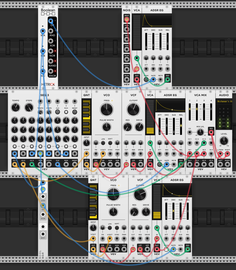
Building on the same patch, a hi-hat voice is added: noise → VCA → ADSR EG (green cables). The Boolean module gates it to only play on steps 3, 5, and 7 of the sequence — the offbeats between the second voice’s steps 1 and 4.
SEQ 3’s third row controls the hi-hat’s volume via the CV3 input on VCA MIX. The knobs on row 3 set per-step levels: steps 3 and 7 are turned up loud, step 5 is quieter. We’re basically controlling the amplitude of different steps of the hi-hat using the CV of the sequencer — not just when it plays but how loud each hit lands. The sequencer is doing triple duty: row 1 handles pitch for the melodic voices, the gate sequencer handles rhythmic masking via boolean logic, and row 3 shapes dynamics.